DR/ES-PTFE
In-Line Detonation Flame Arrester for stable detonations and deflagrations in right angle design with shock absorber, unidirectional
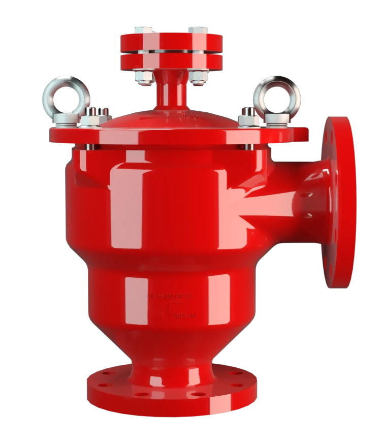
Features
Número reduzido de discos FLAMEFILTER®
Desmontagem e montagem mais rápidas
Design modular
Segurança contra explosões
Corpo angular
Baixos custos
High-Tech Coating of the Housing
Main Component – PROTEGO® Flame Arrester Unit (PTFE)

For Explosion Group IIA
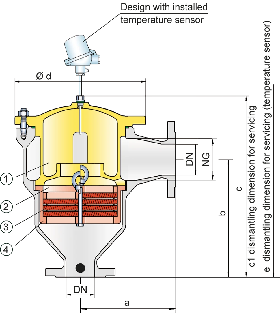
Tabela de dimensões
Para selecionar o diâmetro nominal (DN), utilize os diagramas de vazão nas páginas seguintes
| DN | 40 / 1 ½" | 50 / 2" | 65 / 2 ½" | 80 / 3" | 100 / 4" | 125 / 5" | 150 / 6" |
| a | 153 | 155 | 198 | 200 | 250 | 332 | 335 |
| b | 183 | 185 | 223 | 225 | 290 | 357 | 360 |
| c | 335 | 335 | 420 | 420 | 490 | 590 | 590 |
| c1 | 455 | 455 | 585 | 585 | 680 | 835 | 835 |
| d | 210 | 210 | 275 | 275 | 325 | 460 | 460 |
| e | 685 | 685 | 770 | 770 | 840 | 940 | 940 |
Dimensões em mm
Seleção do grupo de explosão
| MESG | Gr. expl. (IEC / CEN) | Grupo gás (NEC) |
| > 0,90 mm | IIA | D |
Aprovações especiais sob solicitação
Seleção da pressão máx. de trabalho
| DN | 40 / 1 ½" | 50 / 2" | 65 / 2 ½" | 80 / 3" | 100 / 4" | 125 / 5" | 150 / 6" | ||
| Expl. Gr. | IIA | Pmax | 1,1 | 1,1 | 1,2 | 1,2 | 1,1 | 1,1 | 1,1 |
Pmáx. = pressão de trabalho máxima admissível em bar absoluta, pressão de trabalho mais elevada sob solicitação
Indicação da temperatura máx. de trabalho
| ≤ 60°C / 140°F | Ttemperatura máxima de trabalho admissível em °C |
| - | Designation |
temperaturas de trabalho mais elevadas, sob solicitação
Seleção do material do corpo
| Versão | A |
| Corpo | Aço com revestimento em ECTFE |
| Tampa com absorvedor de choque | Aço com revestimento em ECTFE |
| Vedação | PTFE |
| Conjunto abafador de chamas | A, B, C |
Materiais especiais sob solicitação
Combinações de material do conjunto abafador de chamas
| Versão | A | B | C | |
| Armação do jogo de FLAMEFILTER® | PTFE* | Hastelloy | Aço inoxidável | |
| FLAMEFILTER®* | PTFE* | PTFE* | PTFE* | |
| Espaçadores | PEEK / ETFE / FEP | PEEK / ETFE / FEP | PEEK / ETFE / FEP |
*electrically conductive
Tipo de conexão flangeada
| EN 1092-1; Form B1 |
| ASME B16.5 CL 150 R.F. |
Outras conexões sob solicitação
Diagrama de vazão
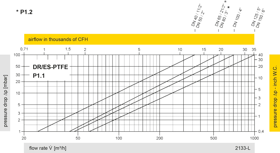
Este diagrama de vazão foi determinado em uma bancada de medição de vazão calibrada e certificada pela TÜV. A vazão V em m³/h se refere ao estado técnico padrão de ar, conforme ISO 6358 (20°C, 1bar). Para conversão em outras densidades e temperaturas, veja o cap. 1: Bases técnicas.


 PROTEGO®
 Representative
 PARC / Service Partner