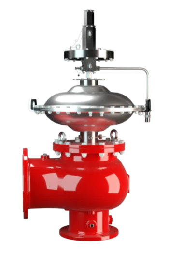
VN-A-PCPF
Pressure/Vacuum Relief Valve, Pilot-operated diaphragm valve
Features
Pilot Operated
Controlled by Corrosion-Resistant Control Valve (Pilot Valve)
Low Emissions
Small Amounts of Tank Substance Is Released Into the Atmosphere When the Valve Is Opened
10% Technology
for Minimum Pressure Increase up to Full Lift
Extreme Tightness
Resulting in Lowest Possible Product Losses and Reduced Environmental Pollution
Optimal Pressure Maintenance
Set Pressure Close to Opening Pressure for Optimum Pressure Maintenance in the System
High Durability
Protection of the Main Valve Control Diaphragm From Low Temperatures – High Durability
Flow Capacity
Optimized Flow Capacity
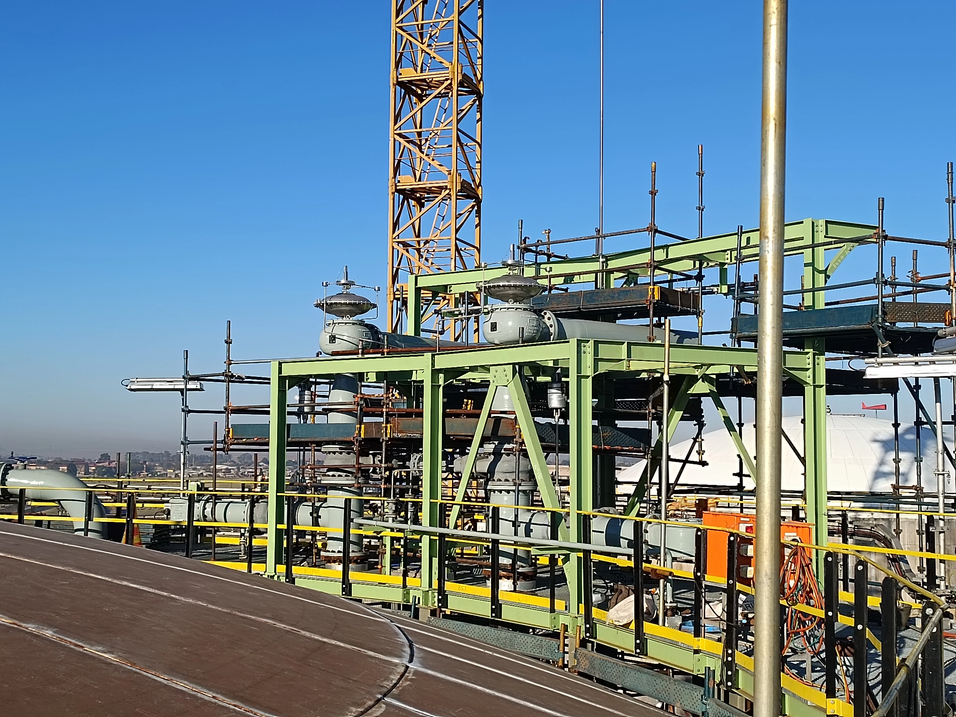
Used in Explosion Hazardous Areas
can Be Used in Explosion Hazardous Areas
Field Test Kit
Field Test and Kit Connection Possible Upon Request
Function and Description
Combined Pressure and Vacuum Relief Valve
The PROTEGO® Type VN-A-PCPF pilot-controlled diaphragm valve is a newly developed valve for pressure and vacuum relief. It is primarily used as a device for out-breathing in tanks, containers, and process equipment. It provides protection against vacuum and overpressure and prevents the intake of air and unallowable product vapor loss up to the set pressure. The valve can also be used as an in-breathing valve where the main valve is directly controlled when it is exposed to a vacuum, i.e., it functions as a weight-loaded diaphragm valve.
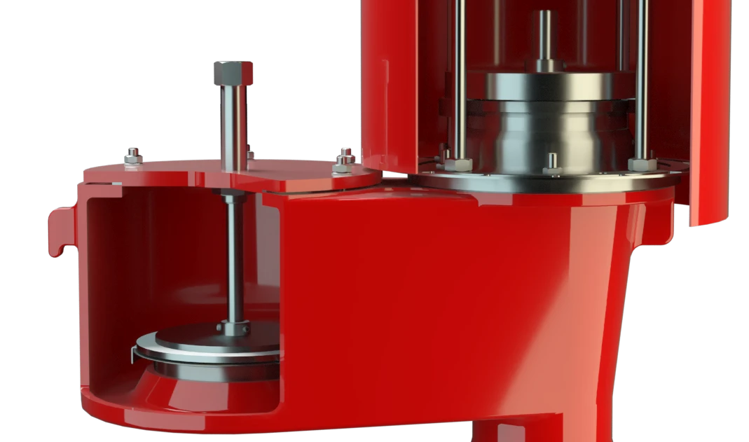
Tank Pressure Controls the Pilot Valve
The main valve is controlled by a pilot valve which is controlled by the tank pressure. A small amount of vapor is released into the atmosphere by the pilot valve when the valve opens. The set pressure is adjusted by increasing or decreasing the tension on the spring on the pilot valve.
Extreme Thightness
As the pressure increases, the closing force on the main valve increases, i.e., the valve becomes tighter with increasing tank pressure until the set pressure is reached. Once the valve has started to lift, it opens fully within a 10% of the pressure increase or opening pressure difference, and the nominal volume flow is released through a fully open valve. If and when this level is exceeded, the pressure increase will follow the performance curve (Δp/V. curve). From set pressure to full capacity (fully open valve), the pressure increase is 100% in case of vacuum venting/in-breathing function.
Advanced Manufacturing Technology
The tank pressure is maintained up to the set pressure with a tightness that is above the normal standards due to our highly developed manufacturing technology. This feature is ensured by valve seats made of high quality stainless steel with precisely lapped valve discs. After the overpressure is released or the vacuum is balanced, the valve re-seats and provides a tight seal.
Product Data
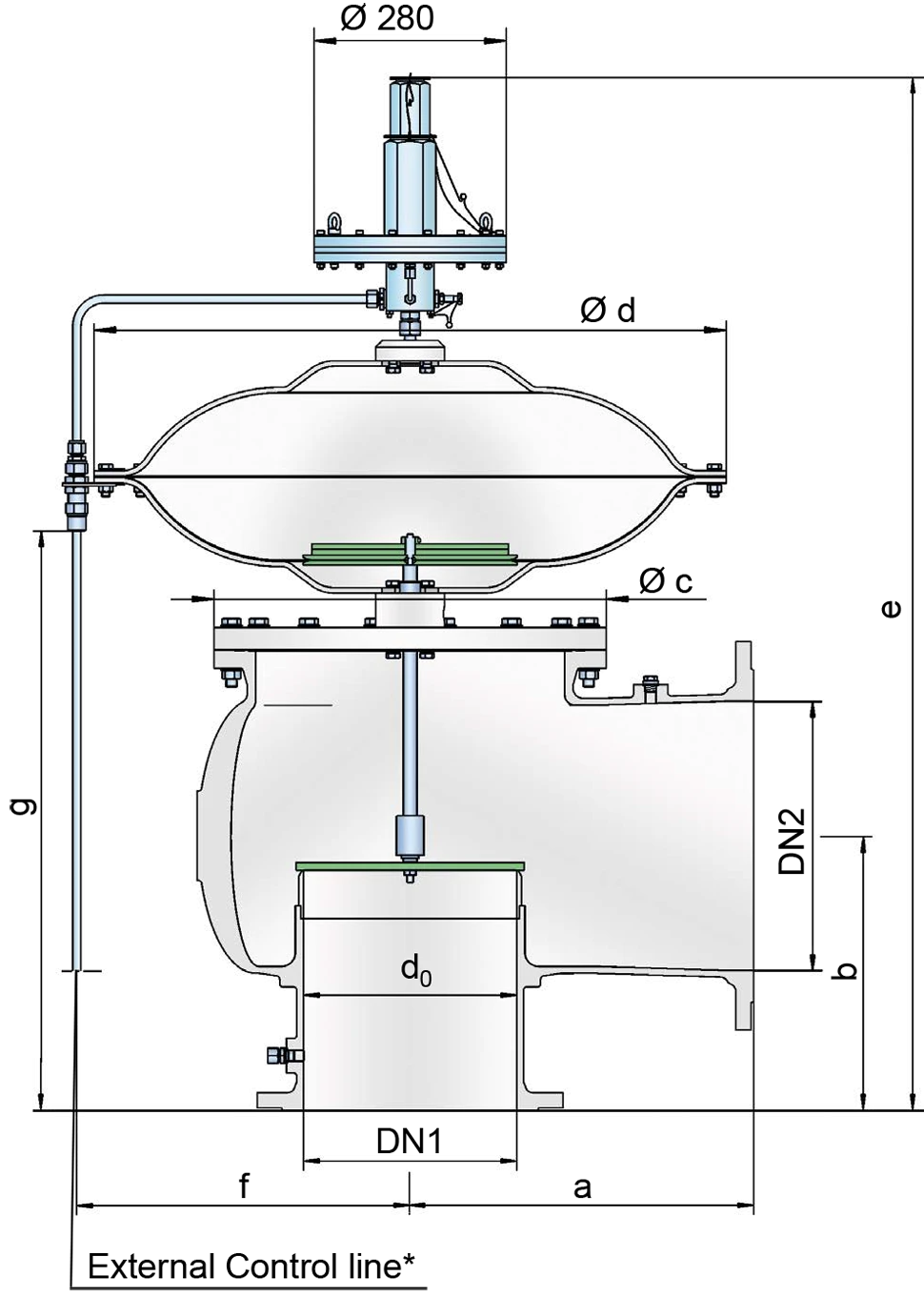
Dimensions
To select the nominal size (DN), use the flow capacity charts on the folloeing pages
| DN1 | DN2 | a | b | c | d | e | f | g |
| 50 / 2" | 50 / 2" | 175 / 6.89 | 175 / 6.89 | 170 / 6.69 | 360 / 14.17 | 916 / 36.06 | 205 / 8.07 | 343 / 13.53 |
| 50 / 2" | 80 / 3" | 175 / 6.89 | 175 / 6.89 | 170 / 6.69 | 360 / 14.17 | 931 / 36.65 | 205 / 8.07 | 358 / 14.09 |
| 80 / 3" | 80 / 3" | 200 / 7.87 | 200 / 7.87 | 205 / 8.07 | 360 / 14.17 | 957 / 37.68 | 205 / 8.07 | 383 / 15.08 |
| 80 / 3" | 100 / 4" | 200 / 7.87 | 200 / 7.87 | 205 / 8.07 | 360 / 14.17 | 967 / 38.07 | 205 / 8.07 | 393 / 15.47 |
| 100 / 4" | 100 / 4" | 225 / 8.86 | 225 / 8.86 | 250 / 9.84 | 360 / 14.17 | 991 / 39.02 | 205 / 8.07 | 418 / 16.46 |
| 100 / 4" | 150 / 6" | 225 / 8.86 | 225 / 8.86 | 250 / 9.84 | 360 / 14.17 | 1001 / 39.41 | 205 / 8.07 | 428 / 16.85 |
| 150 / 6" | 150 / 6" | 300 / 11.81 | 250 / 9.84 | 335 / 13.19 | 500 / 19.69 | 1104 / 43.46 | 275 / 10.83 | 503 / 19.80 |
| 150 / 6" | 200 / 8" | 300 / 11.81 | 250 / 9.84 | 335 / 13.19 | 500 / 19.69 | 1124 / 44.25 | 275 / 10.83 | 523 / 20.59 |
| 200 / 8" | 200 / 8" | 375 / 14.77 | 300 / 11.81 | 410 / 16.14 | 630 / 24.80 | 1237 / 48.70 | 340 / 13.39 | 610 / 24.02 |
| 200 / 8" | 250 / 10" | 375 / 14.77 | 300 / 11.81 | 410 / 16.14 | 630 / 24.80 | 1267 / 49.88 | 340 / 13.39 | 640 / 25.20 |
| 250 / 10" | 250 / 10" | 425 / 16.73 | 350 / 13.78 | 500 / 19.69 | 790 / 31.10 | 1357 / 53.43 | 420 / 16.54 | 710 / 27.96 |
| 250 / 10" | 300 / 12" | 425 / 16.73 | 350 / 13.78 | 500 / 19.69 | 790 / 31.10 | 1377 / 54.41 | 420 / 16.54 | 730 / 28.74 |
| 300 / 12" | 300 / 12" | 500 / 19.69 | 400 / 15.75 | 570 / 22.44 | 920 / 36.22 | 1468 / 57.80 | 485 / 19.09 | 803 / 31.61 |
| 300 / 12" | 350 / 14" | 500 / 19.69 | 400 / 15.75 | 570 / 22.44 | 920 / 36.22 | 1488 / 58.59 | 485 / 19.09 | 823 / 32.40 |
| 300 / 12" | 400 / 16" | 500 / 19.69 | 400 / 15.75 | 570 / 22.44 | 920 / 36.22 | 1508 / 59.37 | 485 / 19.09 | 843 / 33.19 |
Dimensions in mm / inches
Material selection for housing
| Design | A | B | C |
| Housing | Aluminium | Stainless Steel | LTCS* (Low Temperature Carbon Steel) |
| Valve seat | Stainless Steel | Stainless Steel | Stainless Steel |
| Sealing - housing | PTFE | PTFE | PTFE |
| Sealing – valve disc | metal - to - metal | metal - to - metal | metal - to - metal |
| Housing diaphragm | Stainless Steel | Stainless Steel | Stainless Steel |
| Pilot lines | Stainless Steel | Stainless Steel | Stainless Steel |
| Pilot housing | Aluminium | Aluminium/ Stainless Steel | Aluminium/ Stainless Steel |
| Pilot diaphragm | FEP | FEP | FEP |
* Special materials upon request
Flange connection type
| EN 1092-1; Form B1 |
| ASME B16.5 CL 150 R.F. |
Other types upon request
Coefficient of Discharge
| DN1 | 50 / 2" | 50 / 2" | 80 / 3" | 80 / 3" | 100 / 4" | 100 / 4" | 150 / 6" | 150 / 6" | 200 / 8" | 200 / 8" | 250 / 10" | 250 / 10" | 300 / 12" | 300 / 12" | 300 / 12" |
| DN2 | 50 / 2" | 80 / 3" | 80 / 3" | 100 / 4" | 100 / 4" | 150 / 6" | 150 / 6" | 200 / 8" | 200 / 8" | 250 / 10" | 250 / 10" | 300 / 12" | 300 / 12" | 350 / 14" | 400 / 16" |
| d0 | 54 / 2.13 | 54 / 2.13 | 83 / 3.27 | 83 / 3.27 | 108 / 4.25 | 108 / 4.25 | 160 / 6.30 | 160 / 6.30 | 208 / 8.19 | 208 / 8.19 | 262 / 10.31 | 262 / 10.31 | 310 / 12.20 | 310 / 12.20 | 310 / 12.20 |
| K | 0.57 | 0.83 | 0.75 | 0.79 | 0.69 | 0.85 | 0.7 | 0.8 | 0.65 | 0.8 | 0.62 | 0.76 | 0.62 | 0.72 | 0.8 |
DN1 = size inlet
DN2 = size outlet
d0 = orifice diameter(mm / inches)
K = coefficient of discharge
Flow Capacity Chart
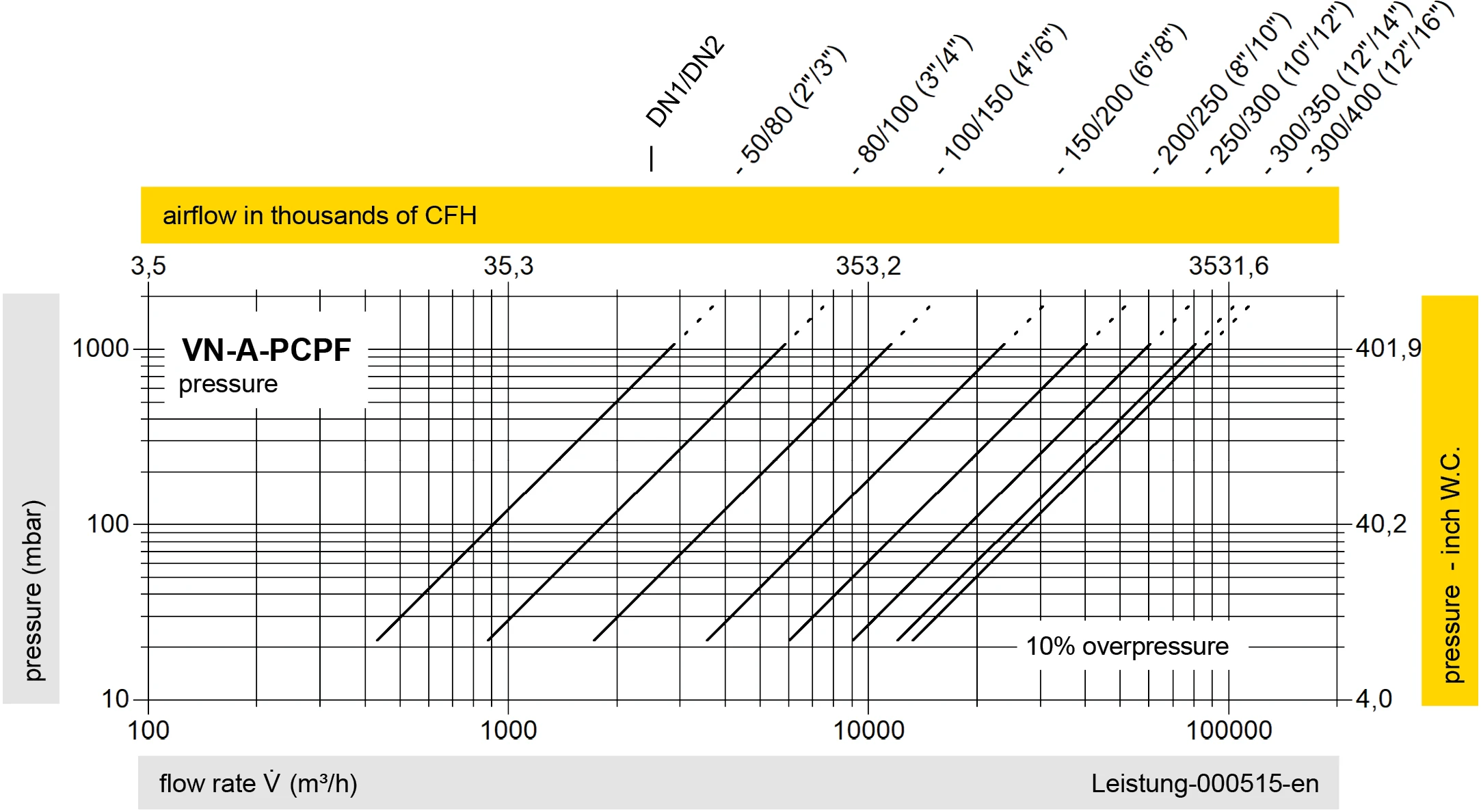
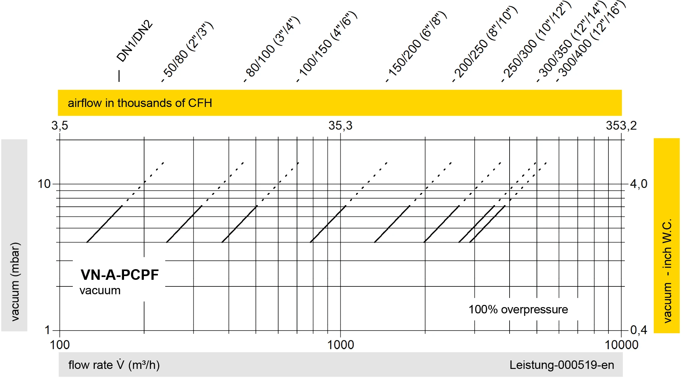
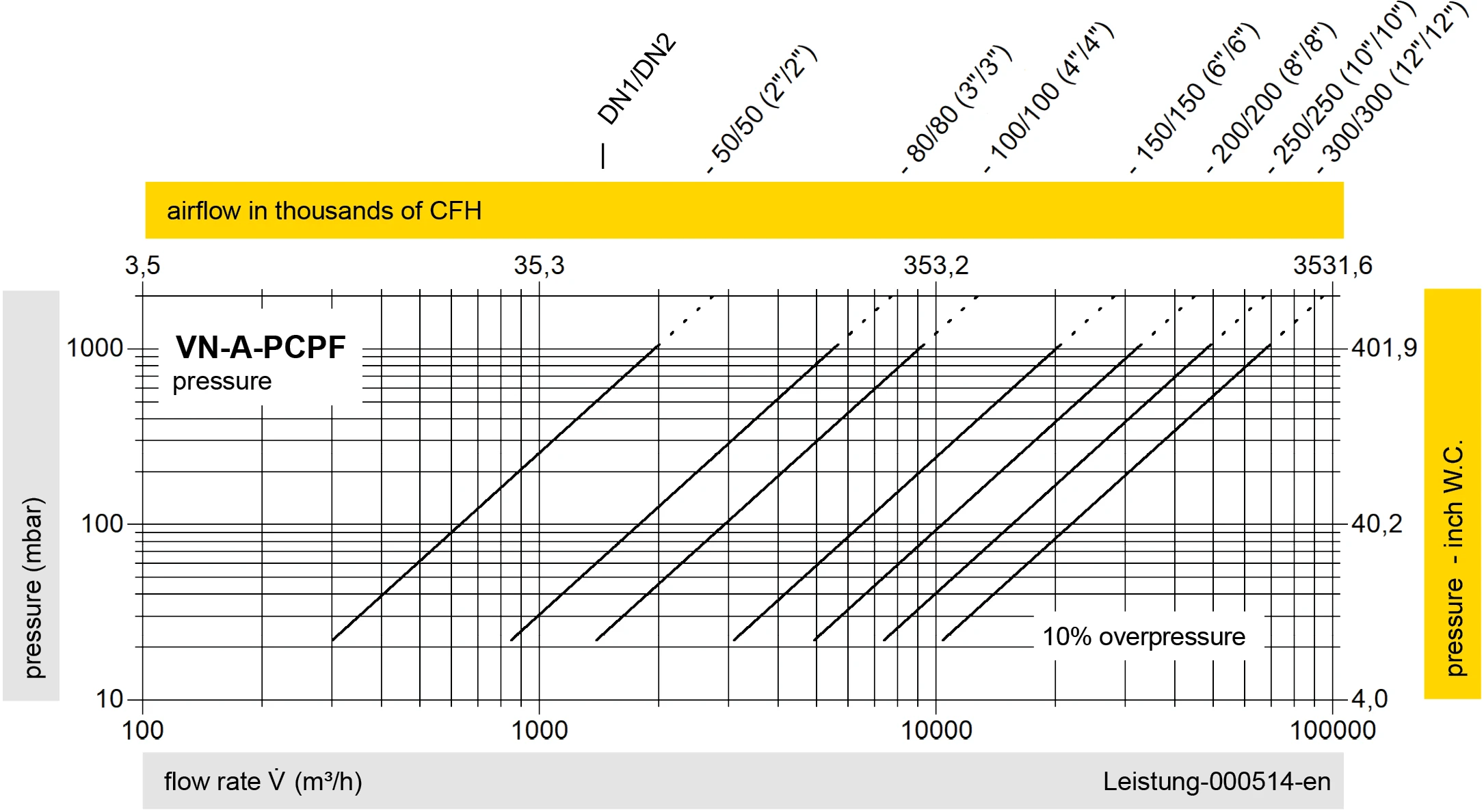
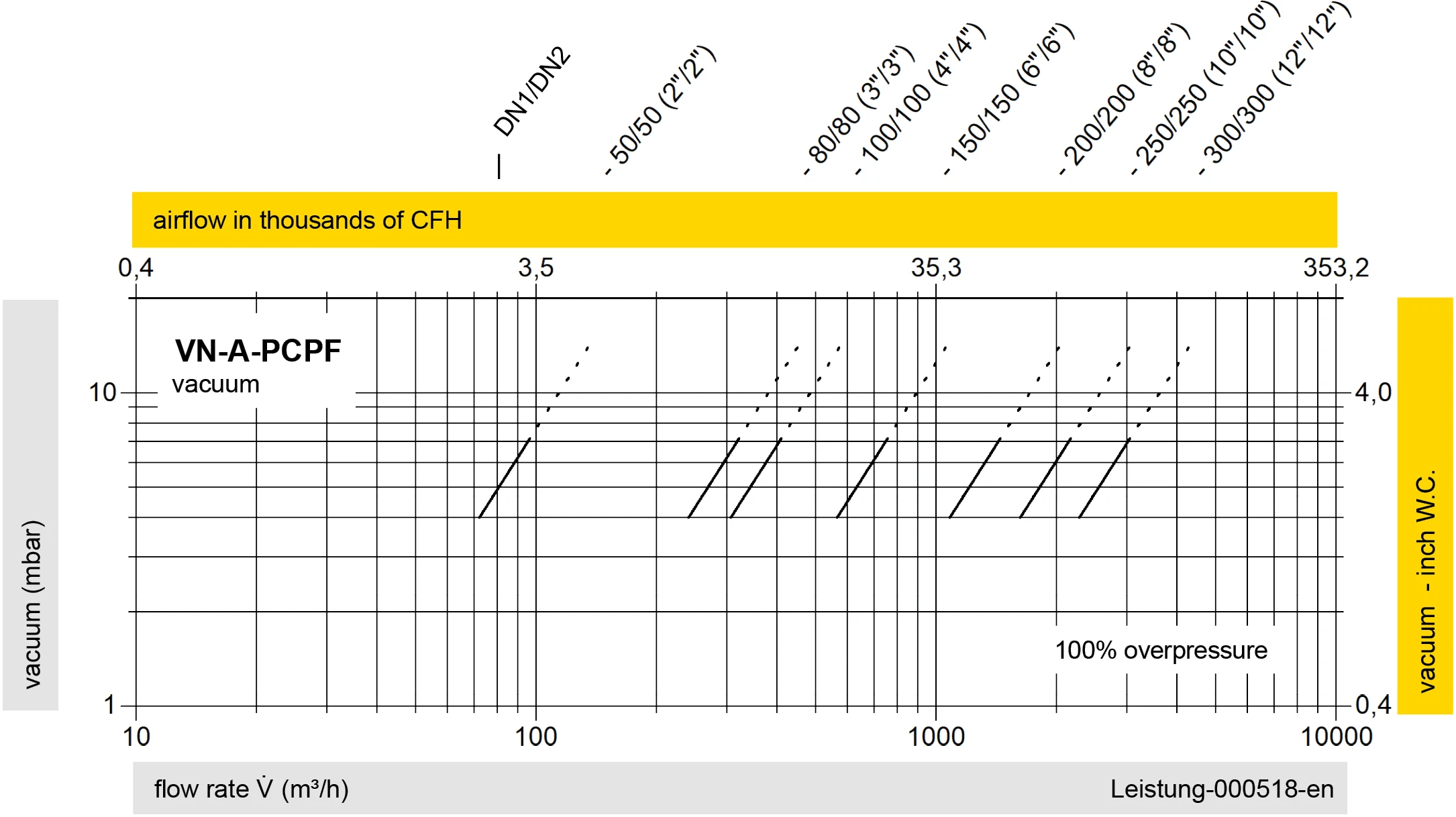
The flow capacity charts have been determined with a calibrated and TÜV certified flow capacity test rig. Volume flow V in (m³/h) and CFH refer to the standard reference conditions of air ISO 6358 (20°C, 1bar). For conversion to other densities and temperatures refer to Sec. 1: “Technical Fundamentals”.