R/KSM
Pressure or Vacuum Relief Valve, In-Line
Features
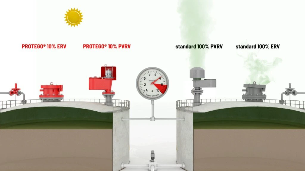
10% Technology
for Minimum Pressure Increase up to Full Lift
Extreme Tightness
Resulting in Lowest Possible Product Losses and Reduced Environmental Pollution
Optimum Pressure Maintenance
Based on 10% Technology, Set Pressure Is Close to Opening Pressure for Optimum Pressure Maintenance in the System as Compared to Conventional 40% or 100% Technology
For Over- and Underpressure
can Be Used as Pressure or Vacuum Relief Valve
Compact Design
Eases Installation Close to Floors and Walls
High Flow Capacity
Reduces Costs Through the Use of Smaller Valves
Non-Corrosive
Weight Reduction
in Comparison to Steel/Stainless Steel
Different Plastics
can Easily Be Combined
Function and Description
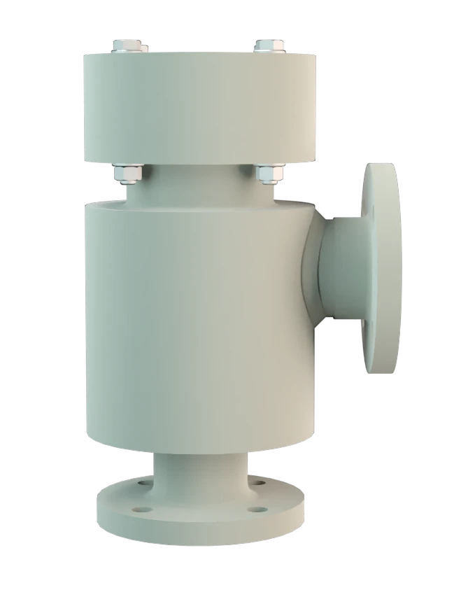
Pressure or Vacuum Relief Valve in Corner Design Made of Plastic
The PROTEGO® In-Line Valve R/KSM is a state-of-the-art Pressure or Vacuum Relief Valve in a right angle design made out of high-grade synthetic material. Typically, the valve is installed in the in-breathing or out-breathing lines of tanks, vessels, and process equipment to protect against unallowable overpressure or underpressure. The valve prevents emission losses almost up to the set pressure and prevents unacceptable product entry. The valve is a perfect solution for corrosive, polymerizing, or sticky substances.
Full Lift Technology
The device will start to open as soon as the set pressure is reached and only requires 10% overpressure to full lift. Continuous investments in and a commitment to research and development have allowed PROTEGO® to develop a low pressure valve which has the same opening characteristic as a high pressure safety relief valve. This “Full Lift Type” technology allows the valve to be set at just 10% below the maximum allowable working pressure or vacuum (MAWP or MAWV) of the tank and still safely vent the required mass flow.
The opening characteristic for pressure and vacuum side is the same.
Advanced Manufacturing Technology
Due to our highly developed manufacturing technology, the tank pressure is maintained up to the set pressure with a tightness that is far above to the conventional standard. This feature is ensured by special valve seats made of high quality synthetic material or PTFE. After the overpressure is released or the vacuum is balanced, the valve re-seats and provides a tight seal.
The optimized fluid dynamic design of the valve body and valve pallet is a result of many years of research, resulting in stable operation of the valve pallet, optimized performance, and reduced product losses.
Product Data
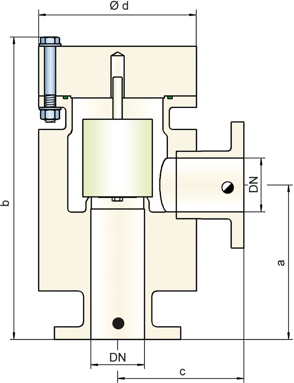
Dimensions
To select the nominal size (DN), please use the flow capacity chart on the following page
| DN | 50 / 2" | 80 / 3" | 100 / 4" | 150 / 6" | 200 / 8" |
| a | 200 / 7.87 | 245 / 9.65 | 300 / 11.81 | 370 / 14.57 | 625 / 24.61 (650 / 25.59)* |
| b | 376 / 14.80 | 521 / 20.51 | 563 / 22.17 (523 / 20.59)* | 687 / 27.05 (651 / 25.63)* | 914 / 35.98 (912 / 35.91)* |
| c | 150 / 5.91 | 200 / 7.87 | 225 / 8.86 | 280 / 11.02 | 350 / 13.78 |
| d | 180 / 7.09 | 250 / 9.84 | 300 / 11.81 | 350 / 13.78 (405 / 15.94)* | 560 / 22.05 (500 / 19.68)* |
Dimensions in mm / inches
* Dimensions in brackets only for PVDF
Material selection for housing
| Design | A | B | C |
| Housing | PE | PP | PVDF |
| Valve seat | PE | PP | PVDF |
| Gasket | FPM | FPM | FPM |
| Valve pallet | A, C, D | B, C, D | C, D |
Special materials upon request
Material selection for valve pallet
| Design | A | B | C | D |
| Pressure range [mbar] [inch W.C.] | ±6,0 up to ±16 ±2.4 up to ±6.4 | ±5,5 up to ±16 ±2.2 up to ±6.4 | ±9,5 up to ±30 ±3.8 up to ±12 | ±30 up to ±100 ±12 up to ±40 |
| Valve pallet | PE | PP | PVDF | Hastelloy |
| Sealing | PTFE | PTFE | PTFE | PTFE |
| Spindle guide | PE | PP | PVDF | Hastelloy |
Special materials and devices with higher set pressure or vacuum are available upon request
Flange connection type
| EN 1092-1; Form B1 |
| ASME B16.5 CL 150 F.F. |
other connections upon request
Flow Capacity Chart
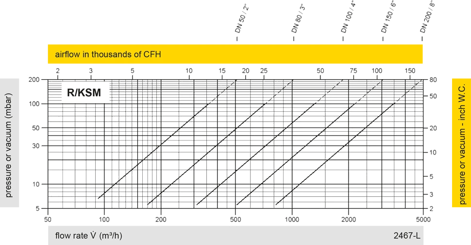
The flow capacity charts have been determined with a calibrated and TÜV certified flow capacity test rig. Volume flow V in (m³/h) and CFH refer to the standard reference conditions of air ISO 6358 (20°C, 1bar). For conversion to other densities and temperatures refer to Sec. 1: “Technical Fundamentals”.

Tank connection for pressure relief function

Tank connection for vacuum relief function