SV/E
Vacuum Relief Valve deflagration-proof
Features
10% Technology
for Minimum Pressure Increase up to Full Lift
Extreme Tightness
Resulting in Lowest Possible Product Losses and Reduced Environmental Pollution
Optimum Pressure Maintenance
Based on 10% Technology, Set Pressure Is Close to Opening Pressure for Optimum Pressure Maintenance in the System as Compared to Conventional 40% or 100% Technology
Flow Capacity
Optimized Flow Capacity
Guided Valve Pallet
Valve Pallet Is Guided Inside the Housing to Protect Against Harsh Weather Conditions
Protective System According to ATEX
can Be Used as a Protective System in Areas With Potentially Explosive Atmosphere in Accordance With ATEX
Modular Design
Allows Replacement and Cleaning of Single FLAMEFILTER®
Lifting Device
Available in a Special Design With Lifting Device (for Ships)
Function and Description
Main Component – PROTEGO® Flame Arrester Unit
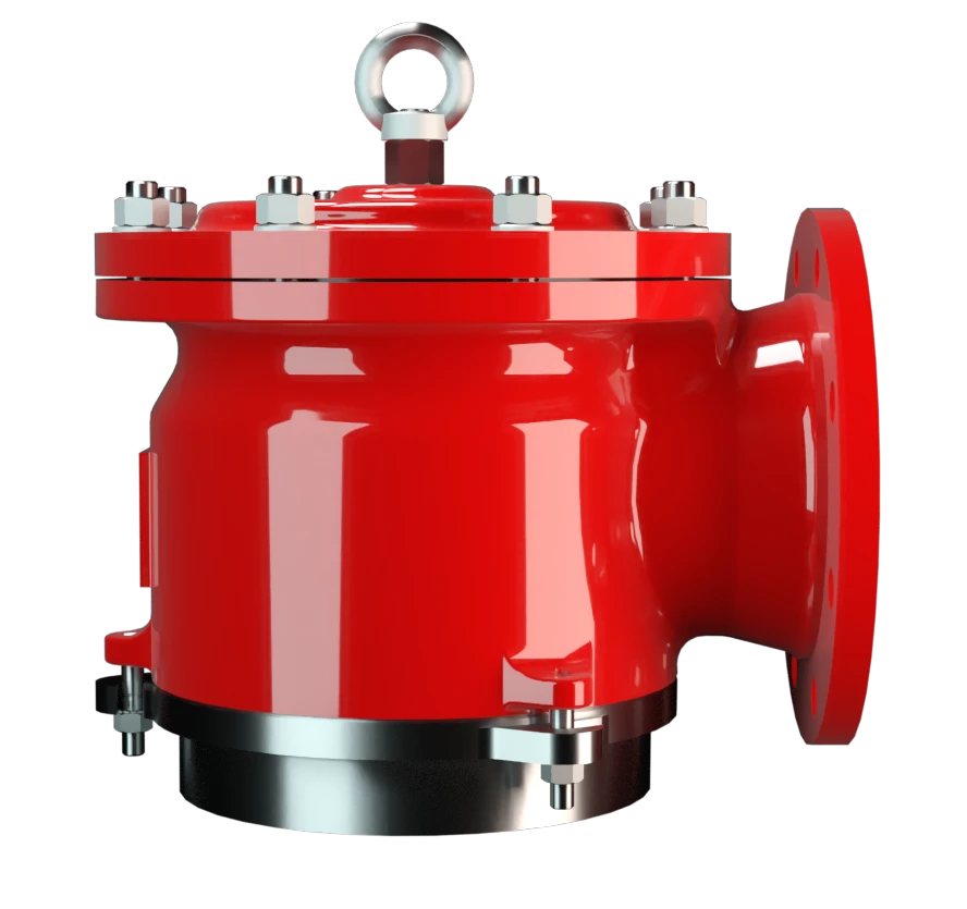
The Deflagration-Proof SV/E Type PROTEGO® valve is a state-of-the-art vacuum relief valve with an integrated Flame Arrester Unit. It is primarily used as a device for flame transmission-proof in-breathing on tanks, containers, and process equipment. The valve offers reliable protection against vacuum and prevents in-breathing of air almost up to the set pressure; while at the same time protecting against atmospheric deflagration. The PROTEGO® Flame Arrester Unit is designed to achieve minimum pressure drop with maximum safety. The PROTEGO® SV/E valve is available for substances from explosion groups IIA to IIC.
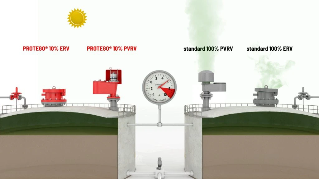
10%-Technology
When the set vacuum is reached, the valve starts to open and reaches full lift within 10% overpressure. This unique 10% technology enables a set vacuum that is only 10% above the maximum allowable working vacuum (MAWV) of the tank. After years of development, this typical opening characteristic of a safety relief valve is now also available for the low pressure range.
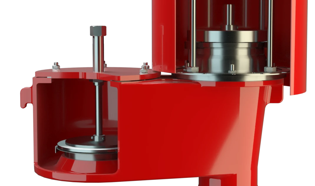
Custom Materials
The tank pressure is maintained up to the set vacuum with a tightness that is above the normal standards due to our state-of-the-art manufacturing technology. This feature is ensured by the valve seats made of high quality stainless steel and with individually lapped valve pallets (1), or with an air cushion seal, (2) in conjunction with high quality FEP diaphragm. The valve pallets are also available with a PTFE seal to prevent them from sticking when sticky substances are used and to enable the use corrosive fluids. After the vacuum is balanced, the valve re-seats and provides a tight seal.
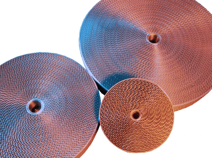
Prevents Ignition Through Integrated FLAMEFILTER®
If the valve is used in atmospheres forming an explosive mixture with air and the mixture ignites, the integrated PROTEGO® Flame Arrester Unit (3) prevents flame transmission into the tank.
The standard design is tested at an operating temperature of up to +60°C / 140°F and meets the requirements of European Tank Design Standard EN 14015 (Appendix L) and ISO 28300 (API 2000). In addition, numerous versions for higher operating temperature are available.

Many Individual Certifications
EU conformity according to the currently valid ATEX directive. Approvals according to other national/international regulations on request. Additional certificates from classification organizations for use on ships are also available.
Product Data
Dimensions
To select the nominal size (DN), please use the flow capacity chart on the following page
| DN | 50 / 2'' | 80 / 3'' | 100 / 4" | 150 / 6'' | 200 / 8'' | 250 / 10'' | 300 / 12'' |
| a | 140 / 5.51 | 170 / 6.69 | 190 / 7.48 | 230 / 9.06 | 300 / 11.81 | 325 / 12.80 | 425 / 16.73 |
| b | 105 / 4.13 | 115 / 4.53 | 125 / 4.92 | 165 / 6.50 | 195 / 7.68 | 230 / 9.06 | 280 / 11.02 |
| c | 225 / 8.86 | 240 / 9.45 | 320 / 12.60 | 410 / 16.14 | 460 / 18.11 | 525 / 20.67 | 575 / 22.64 |
| d | 170 / 6.69 | 235 / 9.25 | 280 / 11.02 | 335 / 13.19 | 445 / 17.52 | 505 / 19.88 | 505 / 19.88 |
| e | 215 / 8.46 | 215 / 8.46 | 255 / 10.04 | 345 / 13.58 | 435 / 17.13 | 470 / 18.50 | 635 / 25.00 |
Dimensions in mm / inches
Selection of explosion group
| MESG | Expl. Gr. (IEC / CEN) | Gas Group (NEC) |
| ≥ 0,65 mm | IIB3 | C |
| ≥ 0,50 mm | IIB | B |
| < 0,50 mm | IIC | B |
Special approvals upon request
Specification of max. operating temperature
| ≤ 60°C / 140°F | Tmaximum allowable operating temperature in °C |
| - | Designation |
higher operating temperatures upon request
Material selection for housing
| Design | B | C | |
| Housing | Steel | Stainless Steel | |
| Heating jacket (SV / E-(S)-H-...) | Steel | Stainless Steel | |
| Valve seat | Stainless Steel | Stainless Steel | |
| Gasket | PTFE | PTFE | |
| Flame arrester unit | B | B |
Special materials upon request
Material combinations of flame arrester unit
| Design | B | |
| FLAMEFILTER® cage | Stainless Steel | |
| Stainless Steel |
Special materials upon request
Material selection for valve pallet
| Design | A | B | C | D | E | F |
| Vacuum range [mbar] [inch W.C.] | -2.0 up to -3.5 -0.8 up to -1.4 | <-3.5 up to -14 <-1.4 up to -5.6 | <-14 up to -35 <-5.6 up to -14 | <-35 up to -60 <-14 up to -24 | <-14 up to -35 <-5.6 up to -14 | <-35 up to -60 <-14 up to -24 |
| Valve pallet | Aluminium | Stainless Steel | Stainless Steel | Stainless Steel | Stainless Steel | Stainless Steel |
| Sealing | FEP | FEP | Metal to Metal | Metal to Metal | PTFE | PTFE |
Special materials and higher pressure settings upon request
Flange connection type
| EN 1092-1; Form B1 |
| ASME B16.5 CL 150 R.F. |
other types upon request
Flow Capacity Chart
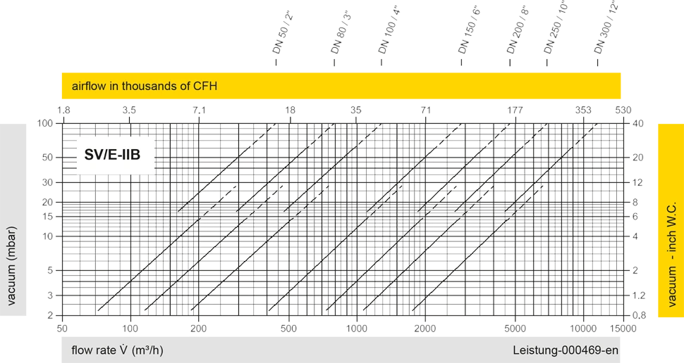
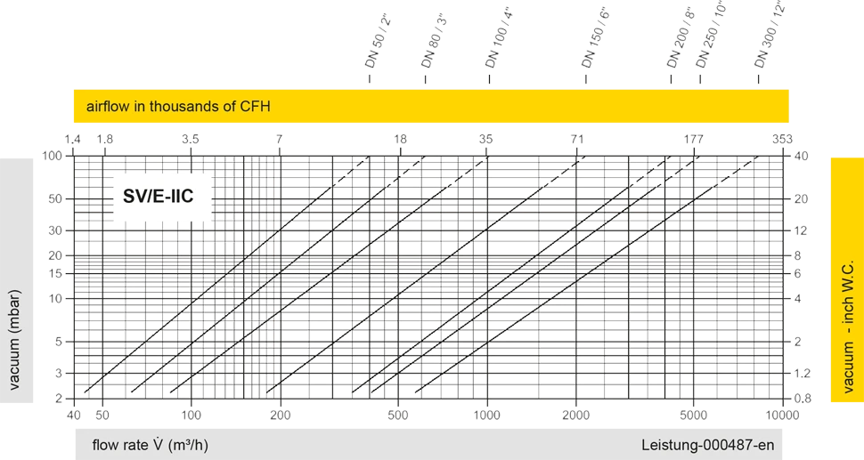
The flow capacity charts have been determined with a calibrated and TÜV certified flow capacity test rig. Volume flow V in (m³/h) and CFH refer to the standard reference conditions of air ISO 6358 (20°C, 1bar). For conversion to other densities and temperatures refer to Sec. 1: “Technical Fundamentals”.


Detail X

Detail X