LH/AD-T
Deflagration Flame Arrester, short time burning-proof, End-of-Line
Features
Comprehensive Weather Protection
Weather Hood With Protection Screen Protects the PROTEGO® Flame Arrester Unit Against Environmental Impact, Such as Nesting Animals and Weather Conditions
Various Sizes
Available for DN 50/2"– bis DN 800/32"– Pipes
Easy Maintenance
Extraordinarily Easy to Service
Extended Application Range
for Elevated Operating Temperatures and Pressures
Low Costs
Low Operating and Lifecycle Costs
Spare Parts
Cost-Effective Spare Parts
Saftey
Provides Protection Against Atmospheric Deflagrations, Short-Time Burning
Function and Description
Protection Against Atmospheric Deflagrations
The PROTEGO® LH/AD-T End-of-Line Deflagration Flame Arrester provides protection against flame transmission through atmospheric deflagration and short time burning on the flame arrester element. The device is typically installed on vent lines of vessels and plant equipment which are not pressurized. The device is equipped with a temperature sensor which immediately detects a flame on the FLAMEFILTER® surface.
Protection Against Short-Time Burning
After the flame is detected, a secondary measure, such as inerting or closing of a shut-off valve to block the vapor flow to the device, should activate within 60 seconds and extinguish the flame so that the system can operate safely. The device prevents flame transmission from short time burning and atmospheric deflagration into the vessel or plant.
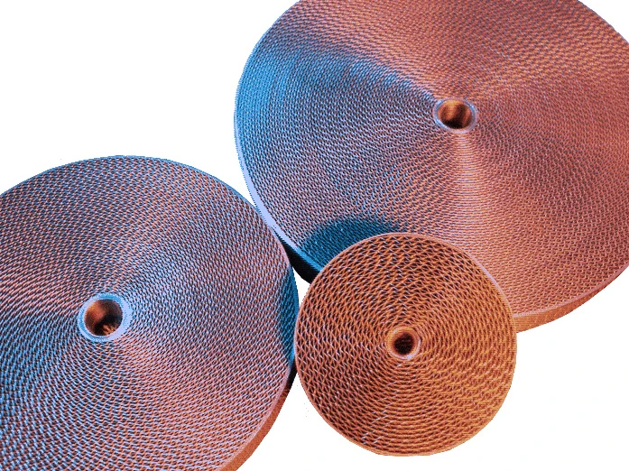
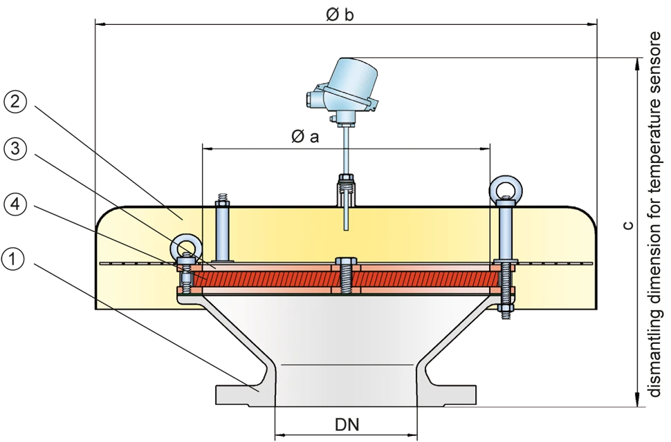
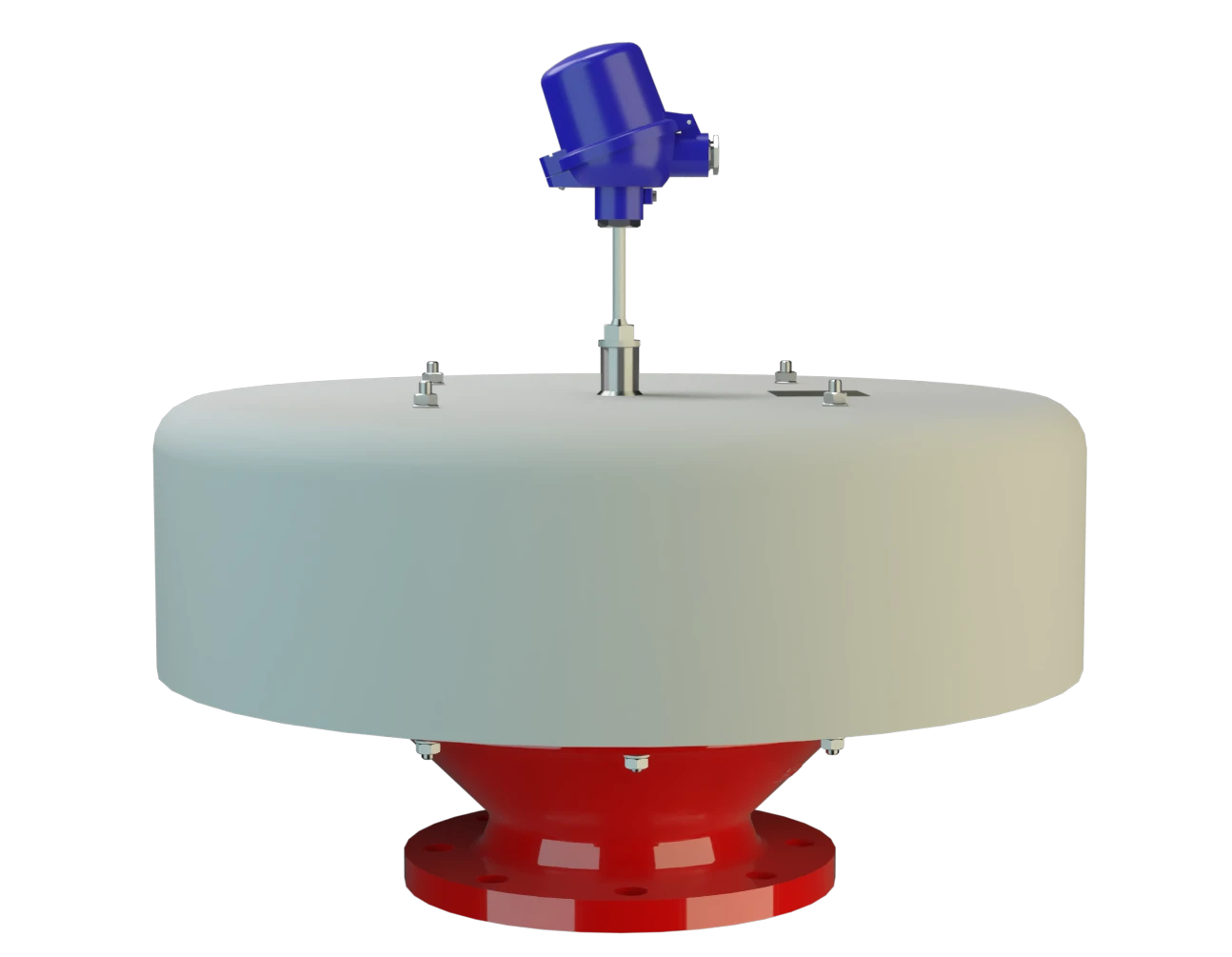
Main Component – PROTEGO® Flame Arrester Unit
The PROTEGO® LH/AD-T consists of the housing (1), a weather hood (2), and the PROTEGO® Flame Arrester Unit (3). The device is equipped with a metal weather hood. The FLAMEFILTER® (4) gap size depends on the device’s intended use. Specifying the operating conditions, such as the temperature, explosion group, and the composition of the fluid, enables PROTEGO® to select the best End-of-Line Deflagration Flame Arrester for your application.

For Explosion Groups IIA to IIC
The PROTEGO® LH/AD-T Series End-of-Line Deflagration Flame Arrester is available for substances from explosion groups IIA to IIC (NEC groups D to B).
The standard design can be used with an operating temperature of up to +60°C / 140°F. Devices with special approval for higher temperatures are available upon request.
EU conformity according to the currently valid ATEX directive. Approvals according to other national/international regulations on request.
Product Data
Dimensions
To select the nominal size (DN), please use the flow capacity charts on the following pages
| DN | a | b | c* | c* |
| IIB3 | IIC | |||
| 50 / 2" | 100 / 3.94 | 240 / 9.45 | 530 / 20.87 | 550 / 21.65 |
| 80 / 3" | 150 / 5.91 | 295 / 11.61 | 560 / 22.05 | 580 / 22.83 |
| 100 / 4" | 200 / 7.87 | 350 / 13.78 | 585 / 23.03 | 605 / 23.82 |
| 150 / 6" | 300 / 11.81 | 600 / 23.62 | 630 / 24.80 | 655 / 25.79 |
| 200 / 8" | 300 / 11.81 | 600 / 23.62 | 630 / 24.80 | 655 / 25.79 |
| 250 / 10" | 400 / 15.75 | 800 / 31.50 | 750 / 29.53 | 770 / 30.31 |
| 300 / 12" | 400 / 15.75 | 800 / 31.50 | 740 / 29.13 | 760 / 29.92 |
| 350 / 14" | 600 / 23.62 | 1000 / 39.37 | 800 / 31.50 | 820 / 32.28 |
| 400 / 16" | 600 / 23.62 | 1000 / 39.37 | 790 / 31.10 | 815 / 32.09 |
| 500 / 20" | 700 / 27.56 | 1200 / 47.24 | 810 / 31.89 | 835 / 32.87 |
| 600 / 24" | 800 / 31.50 | 1200 / 47.24 | 935 / 36.81 | 960 / 37.80 |
| 700 / 28" | 1000 / 39.37 | 1500 / 59.06 | 975 / 38.39 | 995 / 39.17 |
| 800 / 32" | 1200 / 47.24 | 1700 / 66.93 | 1015 / 39.96 | 1035 / 40.75 |
Dimensions in mm / inches
* c are reference values. Exact measures depend on the flange connection.
Selection of explosion group
| MESG | Expl. Gr. (IEC / CEN) | Gas Group (NEC) |
| ≥ 0,65 mm | IIB3 | C |
| < 0,5 mm | IIC | B |
Special approvals upon request
Specification of max. operating temperature
| ≤ 60°C / 140°F | Tmaximum allowable operating temperature in °C |
| - | Designation |
higher operating temperatures upon request
Material selection for housing
| Design | A | B |
| Housing | Steel | Stainless Steel |
| Weather Hood | Stainless Steel | Stainless Steel |
| Protection screen | Stainless Steel | Stainless Steel |
| Flame arrester unit | A, B | B |
Special materials upon request
Material combinations of flame arrester unit
| Design | A | B |
| FLAMEFILTER® cage | Steel | Stainless Steel |
| FLAMEFILTER® | Stainless Steel | Stainless Steel |
Special materials upon request
Flange connection type
| EN 1092-1; Form B1 |
| ASME B16.5 CL 150 R.F. |
other types upon request
Flow Capacity Chart
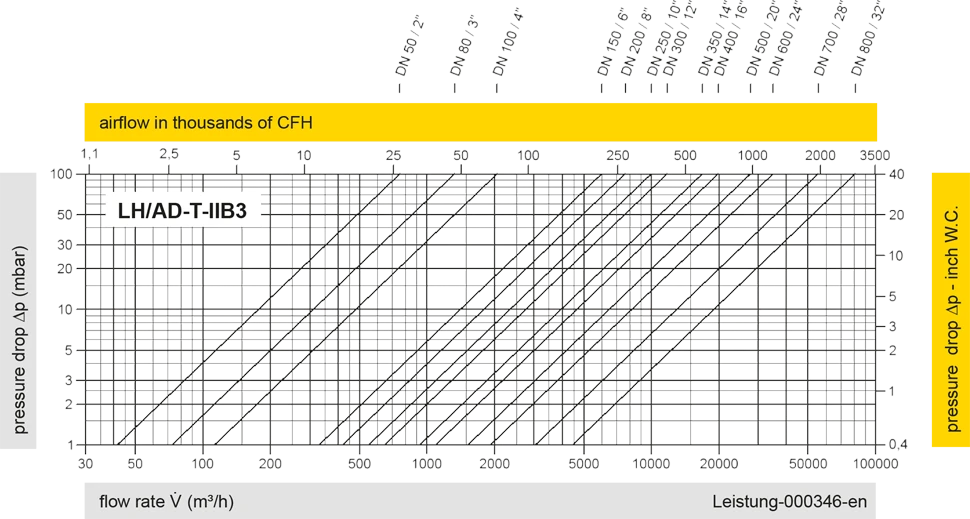
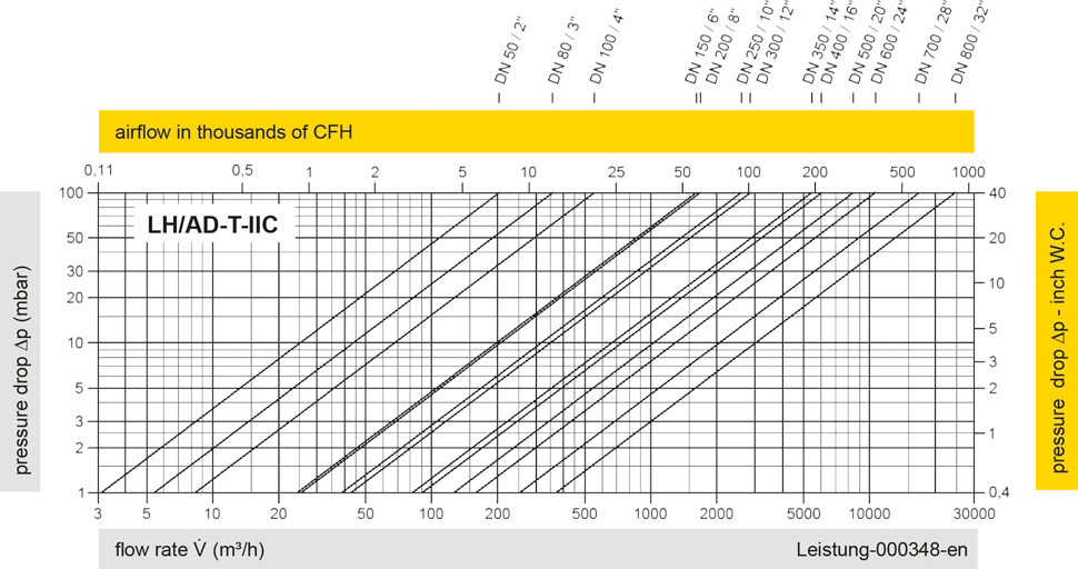
The flow capacity charts have been determined with a calibrated and TÜV certified flow capacity test rig. Volume flow V in (m³/h) and CFH refer to the standard reference conditions of air ISO 6358 (20°C, 1bar). For conversion to other densities and temperatures refer to Sec. 1: “Technical Fundamentals”.