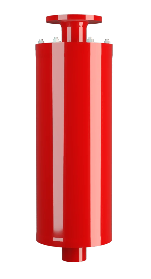
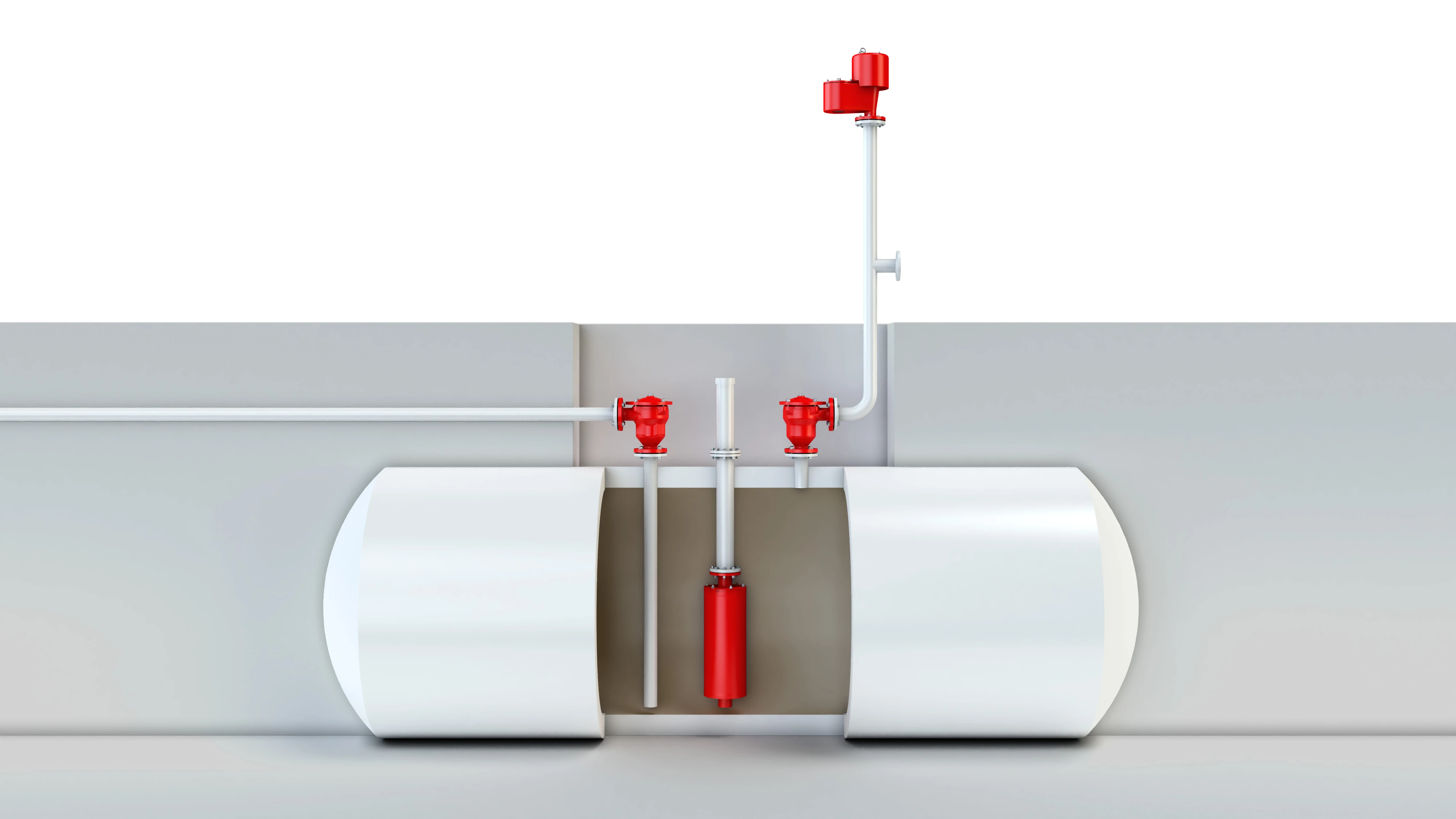
LDA-F
Liquid Detonation Flame Arrester for filling and drain lines - internal installation
Features
Siphon Protection
Low Risk
Low Pressure Loss
For Flammable Liquids
Meets TRGS Requirements
Different Connections
Main Component – PROTEGO® Flame Arrester Unit
Prevention of Flame Spread in Tank During Ignition
Reduction of Flame Propagation Speed

For Explosion Groups IIA to IIB3
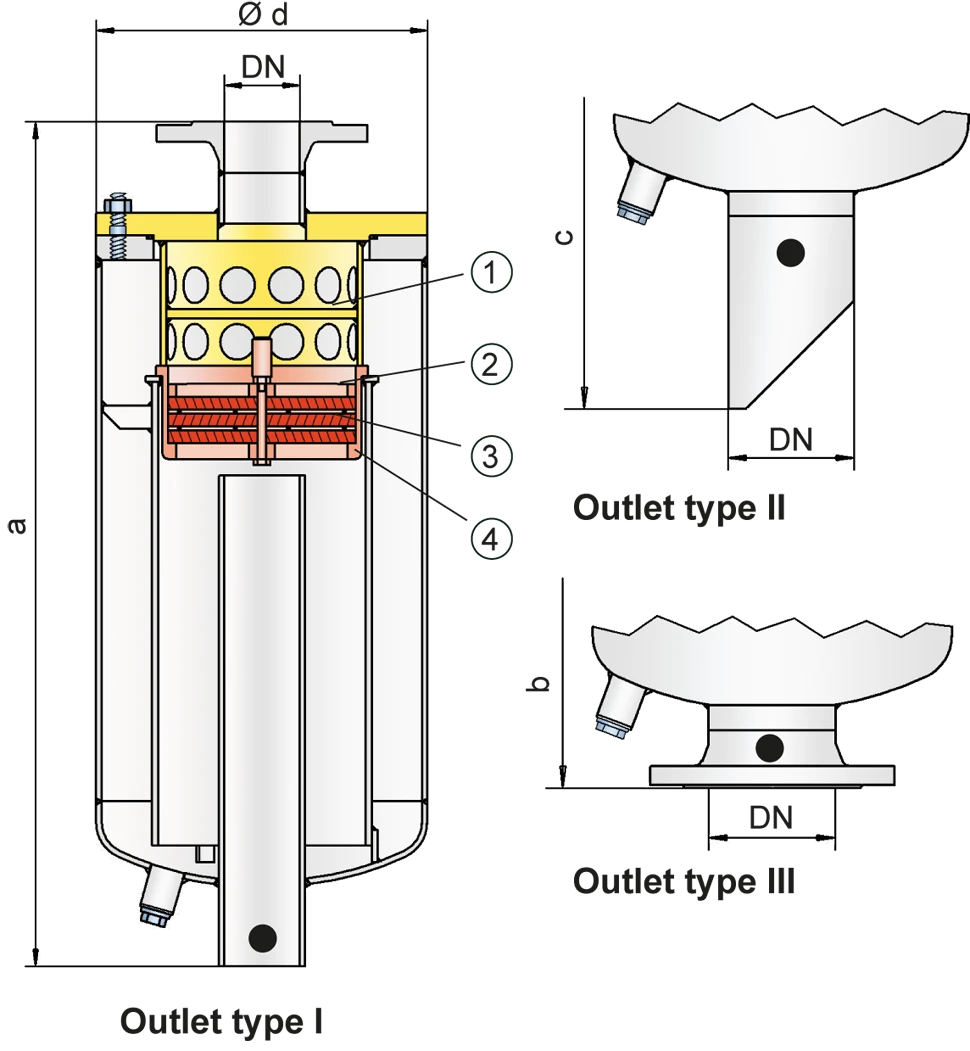
Dimensions
To select the nominal size (DN), please use the flow capacity chart on the following pages
| DN | 25 / 1" | 32 / 1¼“ | 40 / 1½“ | 50 / 2" | 65 / 2½“ | 80 / 3" | 100 / 4" | 125 / 5" | 150 / 6" | 200 / 8" | 250 / 10" |
| a | 550 / 21.65 | 550 / 21.65 | 650 / 25.59 | 650 / 25.59 | 850 / 33.46 | 875 / 34.45 | 1050 / 41.34 | 1250 / 49.21 | 1450 / 57.09 | 1600 / 62.99 | 1975 / 77.76 |
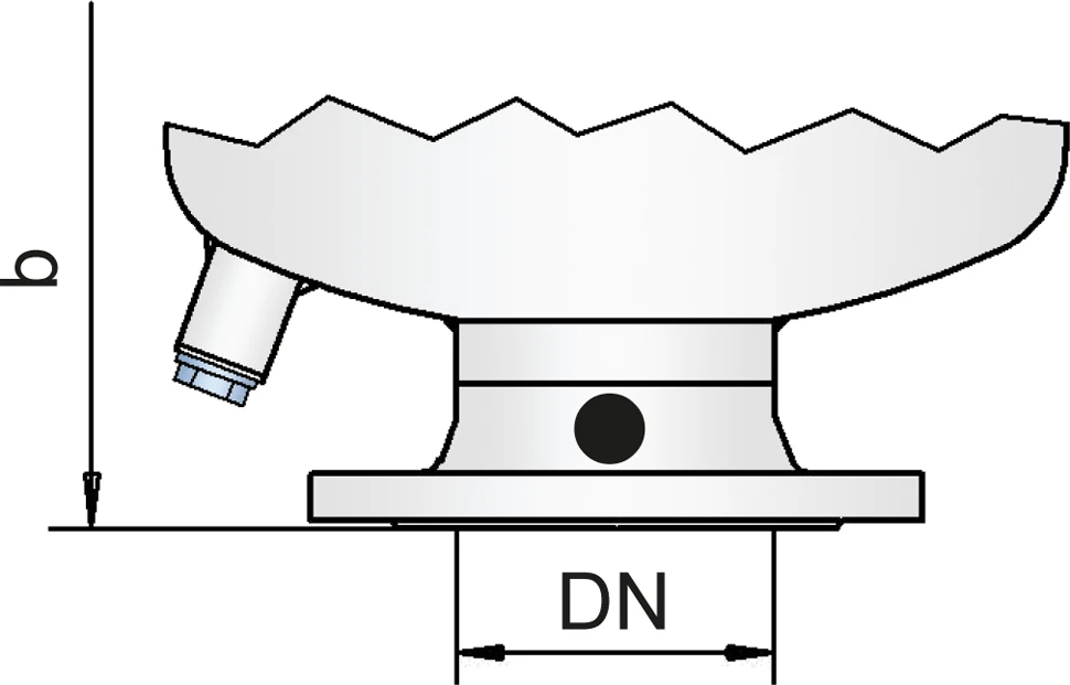
| b | 588 / 23.15 | 590 / 23.23 | 692 / 27.24 | 695 / 27.36 | 895 / 35.24 | 925 / 36.42 | 1102 / 43.39 | 1305 / 51.38 | 1505 / 59.25 | 1662 / 65.43 | 2043 / 80.43 |
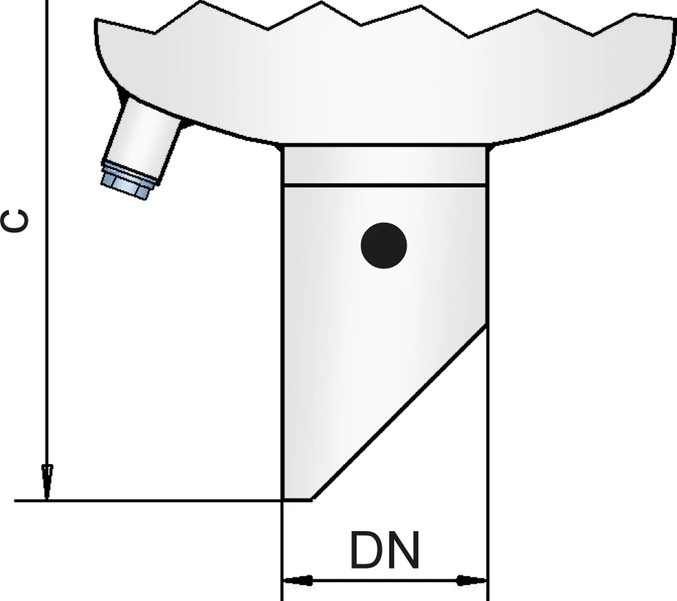
| c | 775 / 30.51 | 775 / 30.51 | 875 / 34.45 | 875 / 34.45 | 1075 / 42.32 | 1095 / 43.11 | 1270 / 50.00 | 1480 / 58.27 | 1680 / 66.14 | 1830 / 72.05 | 2275 / 89.57 |
| d | 140 / 5.51 | 140 / 5.51 | 220 / 8.66 | 220 / 8.66 | 275 / 10.83 | 275 / 10.83 | 356 / 14.07 | 457 / 17.99 | 508 / 20.00 | 600 / 23.62 | 711 / 27.99 |
Dimensions in mm / inches
Selection of explosion group
| MESG | Expl. Gr. (IEC / CEN) | Gas Group (NEC) |
| > 0,90 mm | IIA | D |
| ≥ 0,65 mm | IIB3 | C |
Special approvals upon request
Specification of max. operating temperature
| ≤ 60°C / 140°F | Tmaximum allowable operating temperature in °C |
| - | Designation |
higher operating temperatures upon request
Material selection for housing
| Design | A | B |
| Housing | Steel | Stainless Steel |
| Shock absorber | Steel | Stainless Steel |
| Gasket | FPM | PTFE |
| Flame arrester unit | A | A |
Special materials upon request
Material flame arrester unit
| Design | A |
| FLAMEFILTER® cage | Stainless Steel |
| FLAMEFILTER®* | Stainless Steel |
| Spacer | Stainless Steel |
* the FLAMEFILTER® are also available in the materials Tantalum, Inconel, Copper, etc. when the listed housing and cage materials are used.
Special materials upon request
Flange connection type
| EN 1092-1; Form B1 |
| ASME B16.5 CL 150 R.F. |
other connections upon request
Outlet type
| Straight pipe | I |
| Beveled pipe | II |
| EN 1092-1, Form B1 or DIN 2501, Form C | III (EN or DIN) |
| ASME B16.5 CL 150 R.F. | III (ASME) |
other types upon request
Flow Capacity Chart
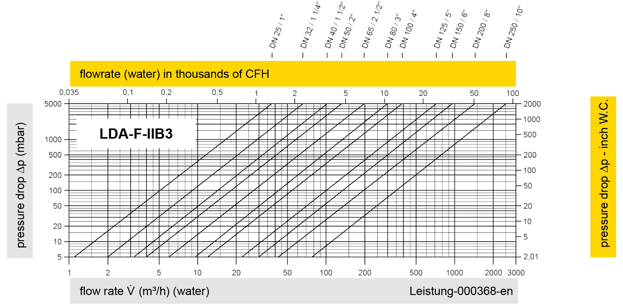
The volume flow V in m³/h was determined with water according to DIN EN 60534 at a temperature Tn = 20°C and an atmospheric pressure pn = 1,013 bar, kinematic viscosity v = 10-6 m²/s
To avoid electrostatic charge of flammable liquids the maximum flow is limited (refer to TRGS 727, CENELEC-Report CLC/TR 60079-32-1).