FA-G
In-Line Deflagration Flame Arrester concentric design, bidirectional

Features
Versatile Application Options
Modular Design
Fastest Disassembly and Assembly
Pipe Thread Connection
Bi-Directional Flame Transmission
Provides Safety
Temperature Sensors Possible
Spare Parts
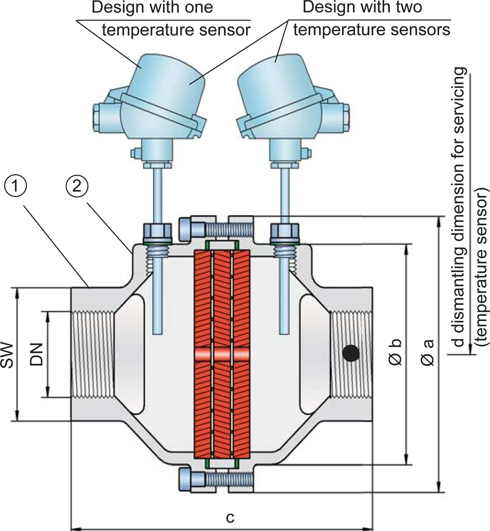
Compact Design of the In-Line Deflagration Flame Arrester
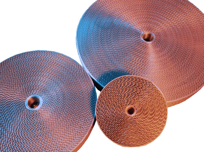
Main Component – PROTEGO® Flame Arrester Unit

Many Individual Certifications
Dimensions
To select the nominal size (DN), use the flow capacity charts on the following pages
| DN | G ½" | G ¾" | G 1" | G 1 ¼" | G 1 ½" | G 2" |
| a | 80 / 3.15 | 80 / 3.15 | 100 / 3.94 | 100 / 3.94 | 155 / 6.10 | 155 / 6.10 |
| b | 55 / 2.17 | 55 / 2.17 | 76 / 2.99 | 76 / 2.99 | 124 / 4.88 | 124 / 4.88 |
| c (IIA bis IIB3) | 100 / 3.94 | 100 / 3.94 | 110 / 4.33 | 110 / 4.33 | 170 / 6.69 | 170 / 6.69 |
| c (IIB und IIC) | 112 / 4.41 | 112 / 4.41 | 122 / 4.80 | 122 / 4.80 | 170 / 6.69 | 170 / 6.69 |
| d | — | — | — | — | 400 / 15.75 | 400 / 15.75 |
| SW | 32 / 1.26 | 32 / 1.26 | 50 / 1.97 | 50 / 1.97 | 75 / 2.95 | 75 / 2.95 |
Dimensions in mm / inches, SW= width across flats
Selection of explosion group
| MESG | Expl. Gr. (IEC / CEN) | Gas Group (NEC) |
| > 0,90 mm | IIA | D |
| ≥ 0,65 mm | IIB3 | C |
| < 0,50 mm | IIC | B |
Special approvals upon request
Selection of max. operating pressure
| Expl. Gr | DN | G ½" | G ¾" | G 1" | G 1¼" | G 1½" | G 2'' |
| IIA | Pmax | 1,4 / 20.3 | 1,4 / 20.3 | 1,4 / 20.3 | 1,4 / 20.3 | 1,5 / 21.7 | 1,5 / 21.7 |
| IIB3 | Pmax | 1,2 / 17.4 | 1,2 / 17.4 | 1,2 / 17.4 | 1,2 / 17.4 | 1,2 / 17.4 | 1,2 / 17.4 |
| IIC | Pmax | 1,1 / 15.9 | 1,1 / 15.9 | 1,1 / 15.9 | 1,1 / 15.9 | 1,1 / 15.9 | 1,1 / 15.9 |
Pmax = maximum allowable operating pressure in bar / psi absolute, higher operating pressure upon request
Specification of max. operating temperature
| ≤ 60°C / 140°F | Tmaximum allowable operating temperature in °C |
| - | Designation |
higher operating temperatures upon request
Material selection
| Design | B | C |
| Housing | Stainless Steel | Hastelloy |
| Gasket | PTFE | PTFE |
| FLAMEFILTER®* | Stainless Steel | Hastelloy |
* the FLAMEFILTER® is also available in the materials Tantalum, Inconel, Copper, etc. when the listed housing materials are used.
Special materials upon request
Type of connection
| Pipe thread DIN ISO 228-1 | DIN |
other types of thread upon request
Flow Capacity Chart
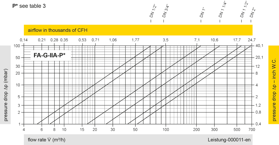
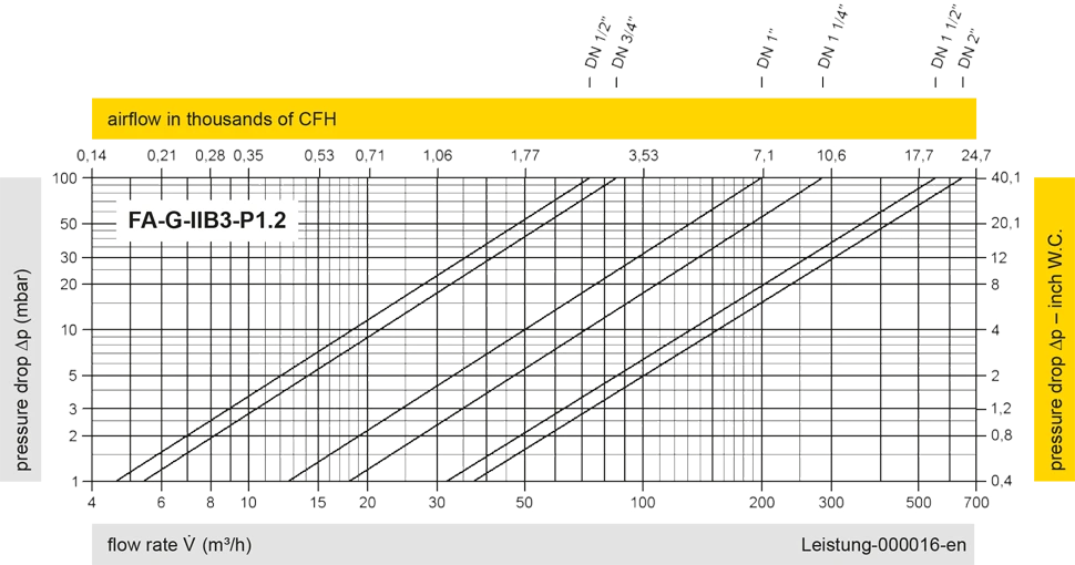
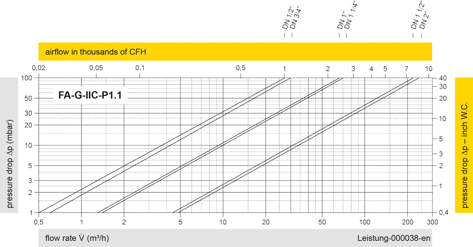
The flow capacity charts have been determined with a calibrated and TÜV certified flow capacity test rig. Volume flow V in (m³/h) and CFH refer to the standard reference conditions of air ISO 6358 (20°C, 1bar). For conversion to other densities and temperatures refer to Sec. 1: “Technical Fundamentals”.