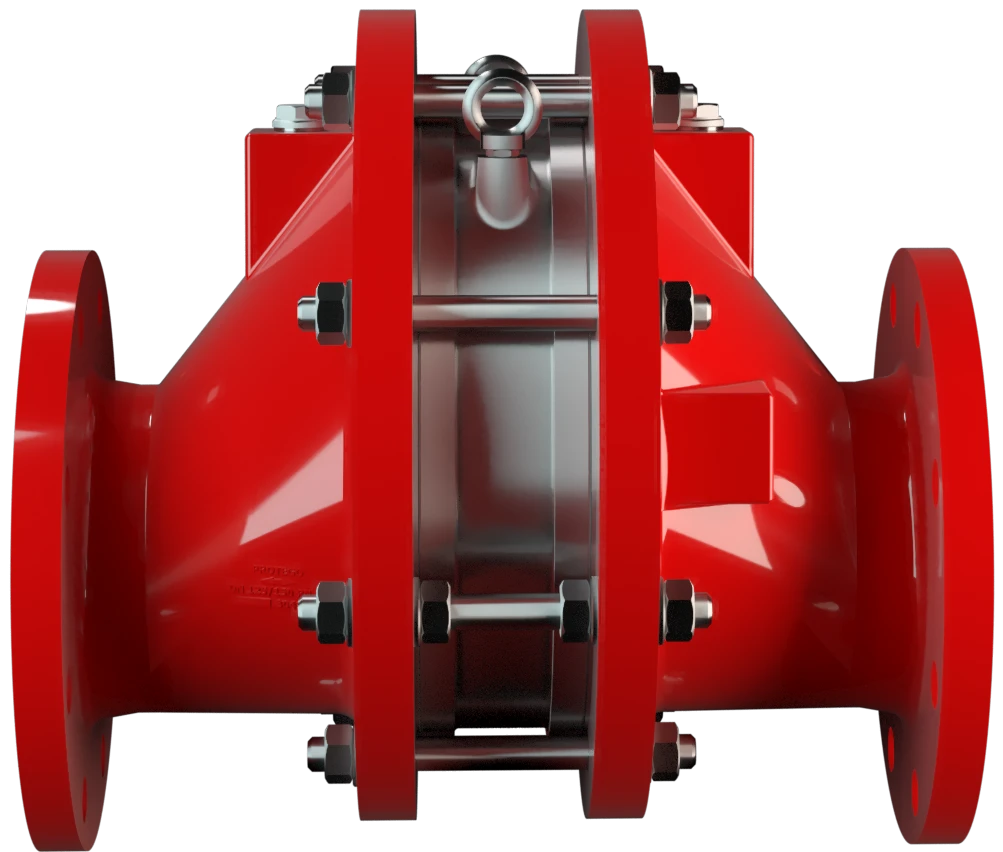
FA-E
In-Line Deflagration Flame Arrester eccentric design, bidirectional
Features
Eccentric Design
Versatile Application Options
Bi-Directional Flame Transmission
Modular Design
Provides Safety
Spare Parts
Excentric Design
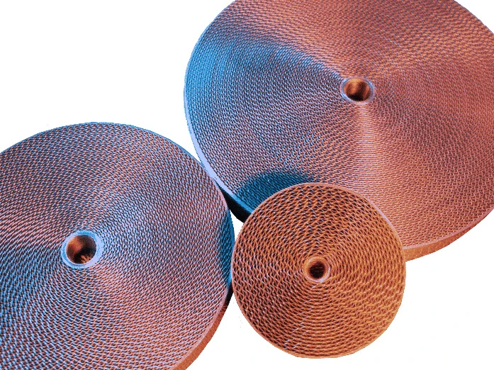
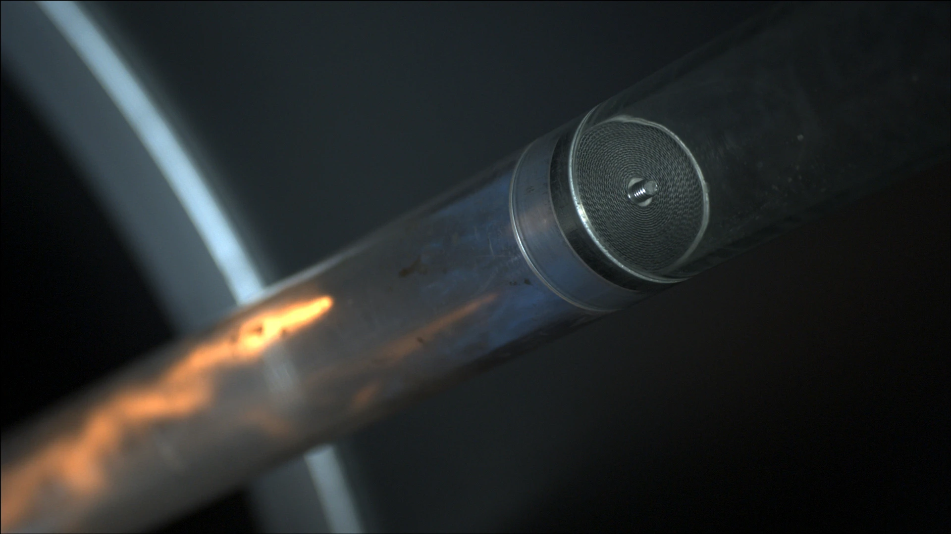
Main Component – PROTEGO® Flame Arrester Unit
For Explosion Group IIA to IIC

Many Individual Certifications
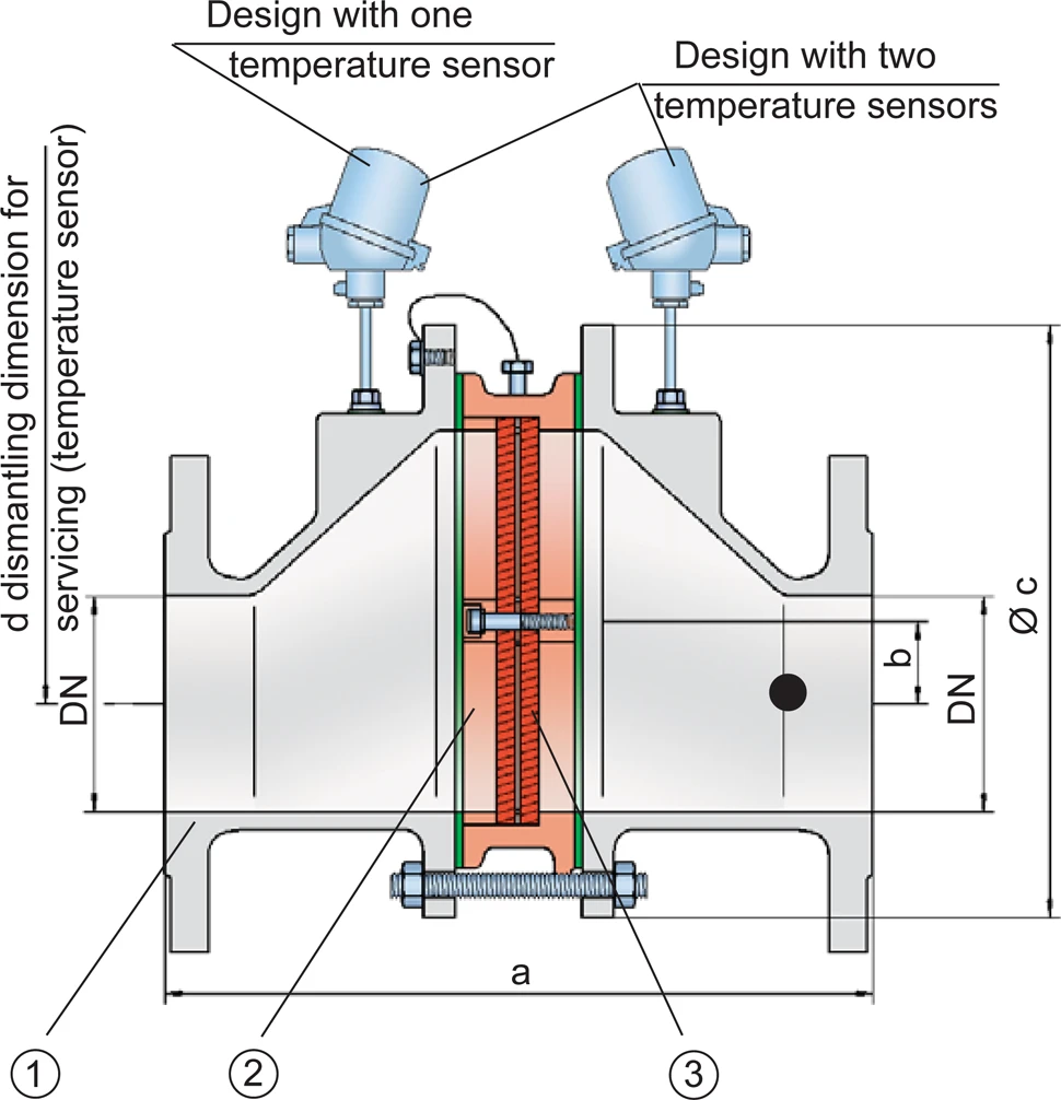
Dimensions
To select the nominal size (DN), use the flow capacity charts on the following pages
| Expl. Gr. | DN | 25 / 1" | 32 / 1¼“ | 40 / 1½“ | 50 / 2" | 65 / 2½“ | 80 / 3" | 100 / 4" | 125 / 5" | 150 / 6" | 200 / 8" | 250 / 10" | 300 / 12" |
| IIA | a | 304 / 11.97 | 304 / 11.97 | 310 / 12.20 | 314 / 12.36 | 360 / 14.17 | 364 / 14.33 | 370 / 14.57 | 434 / 17.09 | 440 / 17.32 | 450 / 17.72 | 480 / 18.90 | 500 / 19.69 |
| IIB3 | a | 304 / 11.97 | 304 / 11.97 | 310 / 12.20 | 314 / 12.36 | 360 / 14.17 | 364 / 14.33 | 370 / 14.57 | 434 / 17.09 | 440 / 17.32 | 450 / 17.72 | 480 / 18.90 | 500 / 19.69 |
| IIC | a | 304 / 11.97 | 304 / 11.97 | 321 / 12.64 | 325 / 12.80 | 371 / 14.61 | 375 / 10.83 | 381 / 15.00 | 445 / 17.52 | 451 / 17.76 | 461 / 18.15 | 491 / 19.33 | 511 / 20.12 |
| b | 29 / 1.14 | 29 / 1.14 | 29 / 1.14 | 29 / 1.14 | 38 / 1.49 | 38 / 1.49 | 39 / 1.53 | 65 / 2.56 | 65 / 2.56 | 55 / 2.17 | 58 / 2.28 | 60 / 2.36 | |
| c | 185 / 7.28 | 185 / 7.28 | 210 / 8.27 | 210 / 8.27 | 250 / 9.84 | 250 / 9.84 | 275 / 10.83 | 385 / 15.16 | 385 / 15.16 | 450 / 17.72 | 500 / 19.69 | 575 / 22.64 | |
| d | 400 / 15.75 | 400 / 15.75 | 410 / 16.14 | 410 / 16.14 | 440 / 17.32 | 440 / 17.32 | 460 / 18.11 | 520 / 20.47 | 520 / 20.47 | 540 / 21.26 | 570 / 22.44 | 600 / 23.62 |
Dimensions in mm / inches
Selection of explosion group
| MESG | Expl. Gr. (IEC / CEN) | Gas Group (NEC) |
| > 0,90 mm | IIA | D |
| ≥ 0,65 mm | IIB3 | C |
| < 0,50 mm (> 0,50 mm) | IIC (IIB) | B |
Special approvals upon request
Selection of max. operating pressure
| Expl. Gr. | DN | 25 / 1" | 32 / ¼" | 40 / 1½" | 50 / 2" | 65 / 2½" | 80 / 3" | 100 / 4" | 125 / 5" | 150 / 6" | 200 / 8" | 250 / 10" | 300 / 12" |
| IIA | Pmax | 1,6 / 23.2 | 1,6 / 23.2 | 1,6 / 23.2 | 1,6 / 23.2 | 1,6 / 23.2 | 1,6 / 23.2 | 1,6 / 23.2 | 1,6 / 23.2 | 1,6 / 23.2 | 1,6 / 23.2 | 1,6 / 23.2 | 1,6 / 23.3 |
| IIB3 | Pmax | 1,6 / 23.3 | 1,6 / 23.3 | 1,6 / 23.3 | 1,6 / 23.3 | 1,6 / 23.3 | 1,6 / 23.3 | 1,6 / 23.3 | 1,6 / 23.3 | 1,6 / 23.3 | 1,6 / 23.3 | 1,6 / 23.3 | 1,6 / 23.3 |
| IIC | Pmax | 1,1 / 15.9 | 1,1 / 15.9 | 1,1 / 15.9 | 1,1 / 15.9 | 1,1 / 15.9 | 1,1 / 15.9 | 1,2 / 15.9 | 1,1 / 15.9 | 1,1 / 15.9 | 1,1 / 15.9 | 1,1 / 15.9 | 1,1 / 15.9 |
Pmax = maximum allwowable operating pressure in bar / psi (absolute), higher operating pressure upon request
Specification of max. operating temperature
| ≤ 60°C / 140°F | Tmaximum allowable operating temperature in °C |
| - | Designation |
higher operating temperatures upon request
Material selection for housing
| Design | B | C | D |
| Housing | Steel | Stainless Steel | Hastelloy |
| Gasket | PTFE | PTFE | PTFE |
| Flame arrester unit | A,C | C | D |
The housing can also be delivered in carbon steel with an ECTFE coating.
Special materials upon request
Material combinations of flame arrester unit
| Design | A | C | D |
| FLAMEFILTER® cage | Steel | Stainless Steel | Hastelloy |
| FLAMEFILTER®* | Stainless Steel | Stainless Steel | Hastelloy |
| Spacers | Stainless Steel | Stainless Steel | Hastelloy |
*the FLAMEFILTER® is also available in the materials Tantalum, Inconel, Copper, etc. when the listed housing and cage materials are used
Special materials upon request.
Flange connection type
| EN 1092-1; Form B1 |
| ASME B16.5 CL 150 R.F. |
other connections upon request
Flow Capacity Chart
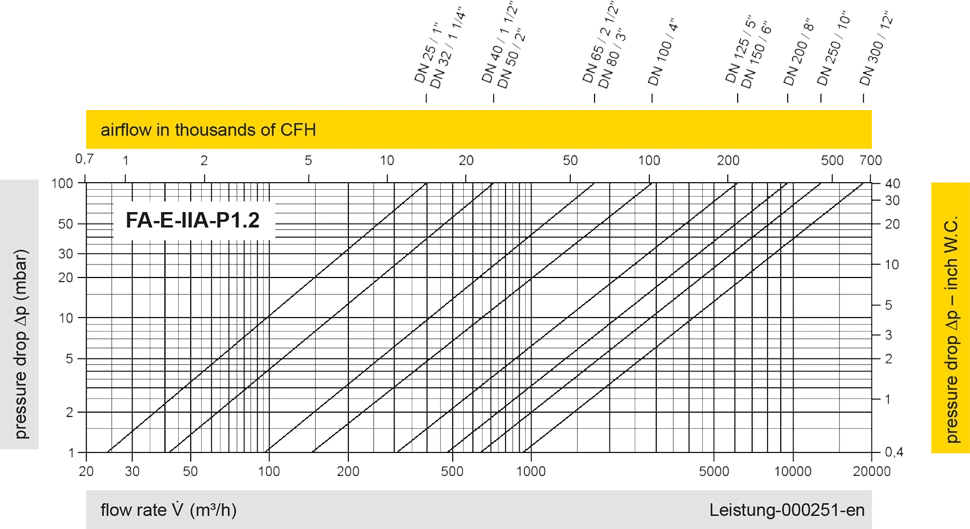
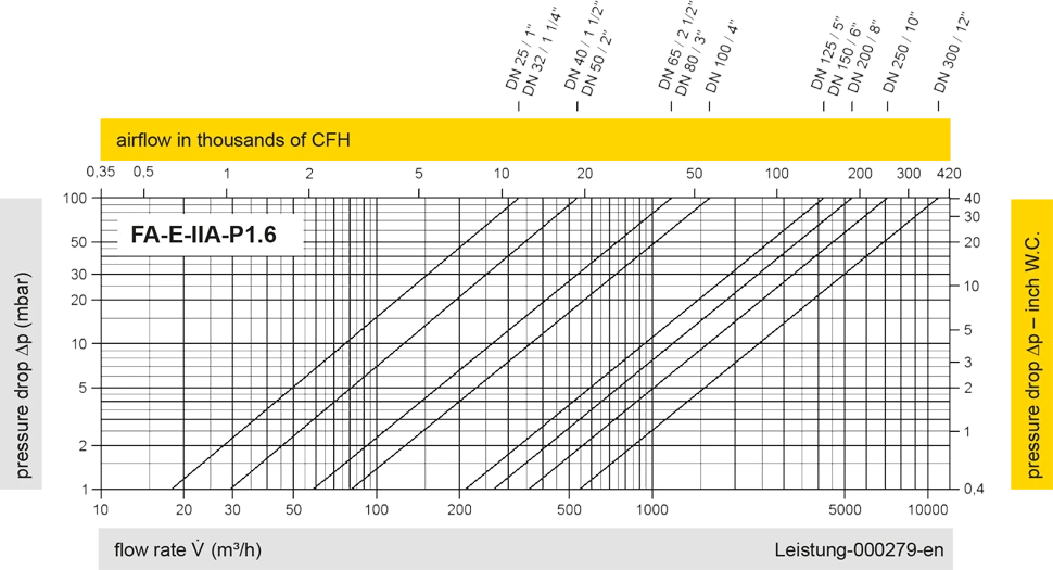
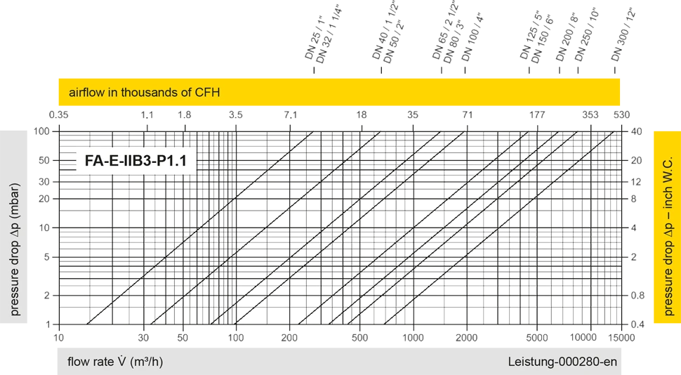
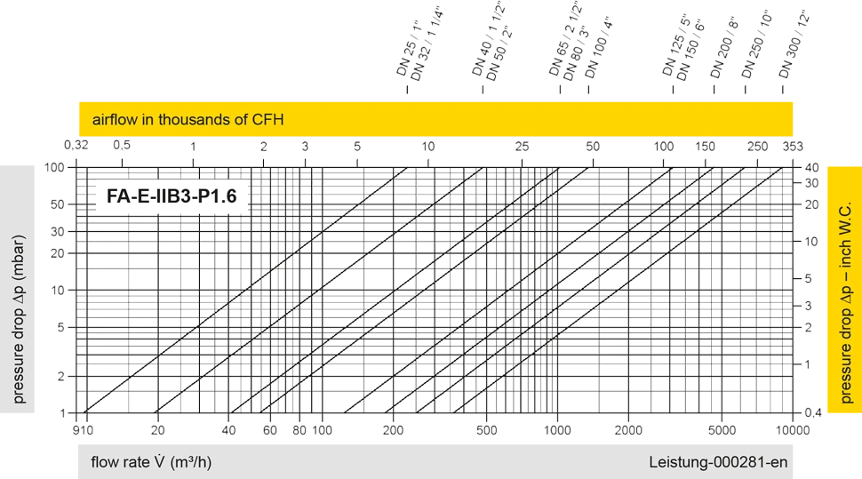
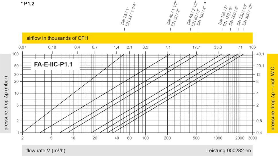
The flow capacity charts have been determined with a calibrated and TÜV certified flow capacity test rig. Volume flow V in (m³/h) and CFH refer to the standard reference conditions of air ISO 6358 (20°C, 1bar). For conversion to other densities and temperatures refer to Sec. 1: “Technical Fundamentals”.