EB-Z
Deflagration Flame Arrester, endurance burning proof, End-of-Line
Features
Safety Against Deflagrations and Hydrocarbon Fires
Provides Protection Against Atmospheric Deflagrations, Short-Time Burning and Endurance Burning of Pure Hydrocarbons
Comprehensive Weather Protection
Weather Hood With Protection Screen Protects the PROTEGO® Flame Arrester Unit Against Environmental Impact, Such as Nesting Animals and Weather Conditions
Modular Design
Allows Replacement and Cleaning of Single FLAMEFILTER®
Easy Maintenance
Without Disassembling of the FLAMEFILTER®
Low Costs
Low Operating and Lifecycle Costs
Spare Parts
Cost-Effective Spare Parts
Function and Description
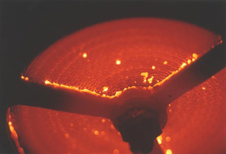
Protection Against Atmospheric Deflagration and Endurance Burning
The PROTEGO® EB-Z End-of-Line Deflagration Flame Arrester has been successfully used to protect small vessels and process engineering apparatus which are not pressurized. The device provides protection against flame transmission through atmospheric deflagration and stabilized flames which can burn for very long time on the flame arrester element surface, so called endurance burning. Main application area is on in- and outbreathing vent lines, with the goal to prevent flame transmission caused by endurance burning or atmospheric deflagration from propagating into the vessel or plant.
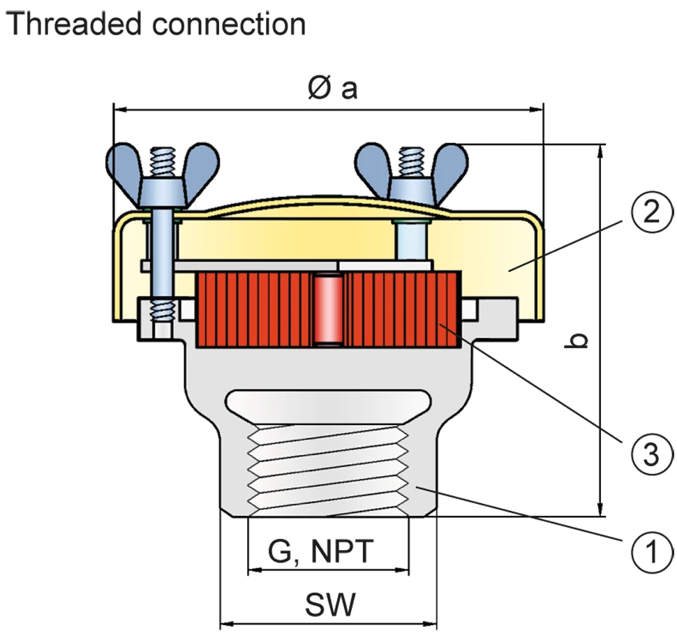
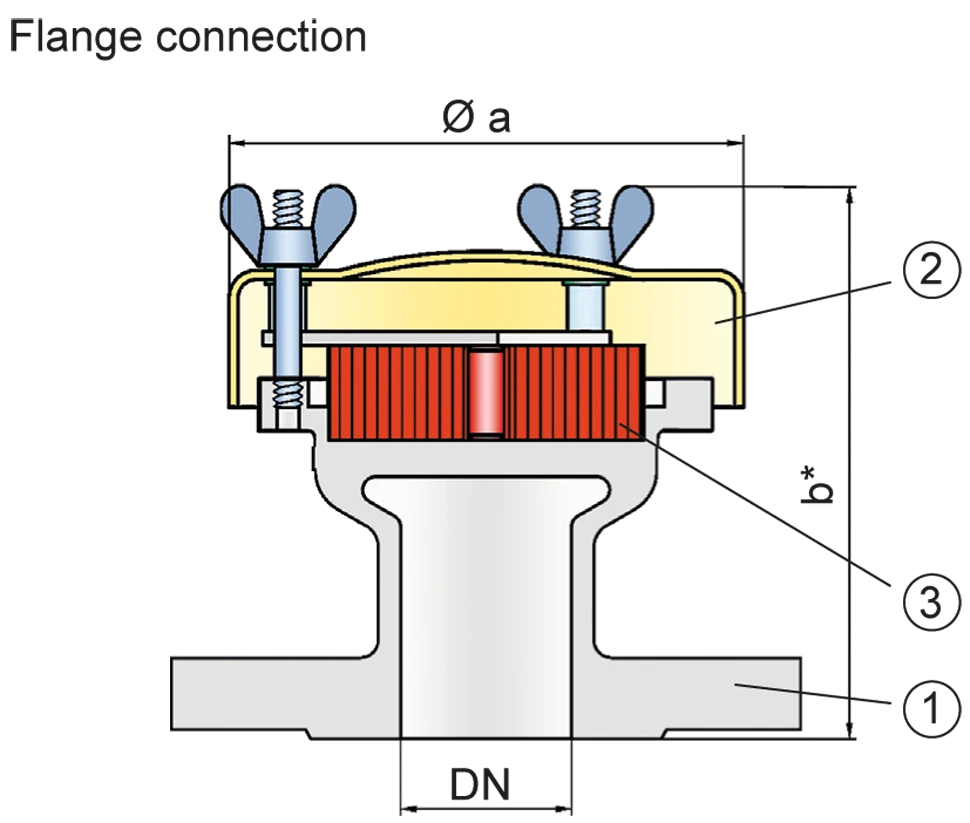
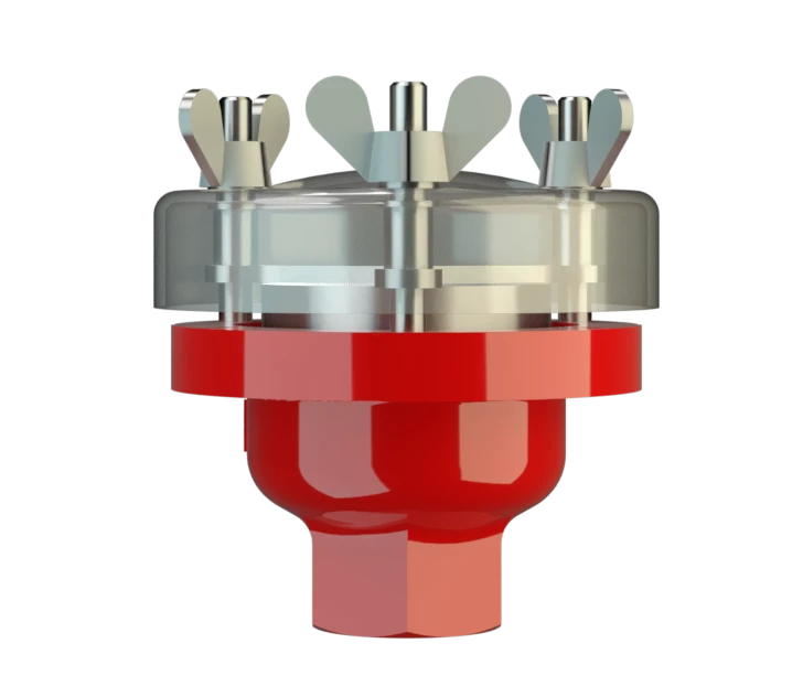
Main Component – PROTEGO® Flame Arrester Unit
The PROTEGO® EB-Z consists of a housing (1), a weather hood (2) and the FLAMEFILTER® (3). The weather hood is made out of acrylic glass, which will melt when impacted by flames and allow heat to dissipate to the environment. The PROTEGO® EB-Z Series End-of-Line Deflagration Flame Arrester is available for substances of explosion group IIA (NEC group D MESG > 0.90 mm)

Many Individual Certifications
The standard design can be used for operating temperatures up to +60°C / 140°F.
EU conformity according to the currently valid ATEX directive. Approvals according to other national/international regulations on request.
Product Data
Dimensions
To select the nominal size (DN), please use the flow capacity chart
| DN/ G, NPT | 15 / ½“ | 20 / ¾" | 25 / 1“ | 32 / 1¼“ |
| a | 87 | 87 | 114 | 114 |
| b | 93 | 93 | 98 | 98 |
| b* | 123 | 123 | 123 | 123 |
| SW | 32 | 32 | 50 | 50 |
Dimensions in mm / inches, SW= width across flats
Selection of explosion group
| MESG | Expl. Gr. (IEC / CEN) | Gas Group (NEC) |
| > 0,90 mm | IIA | D |
Special approvals upon request
Material selection
| Design | B |
| Housing | Stainless Steel |
| Weather Hood | Acrylic glass |
| FLAMEFILTER® | Stainless Steel |
Special materials upon reques
Type of connection
| Pipe thread DIN ISO 228-1 |
| EN 1092-1; Form B1 |
| ASME B16.5 CL 150 R.F. |
other types upon request
Flow Capacity Chart
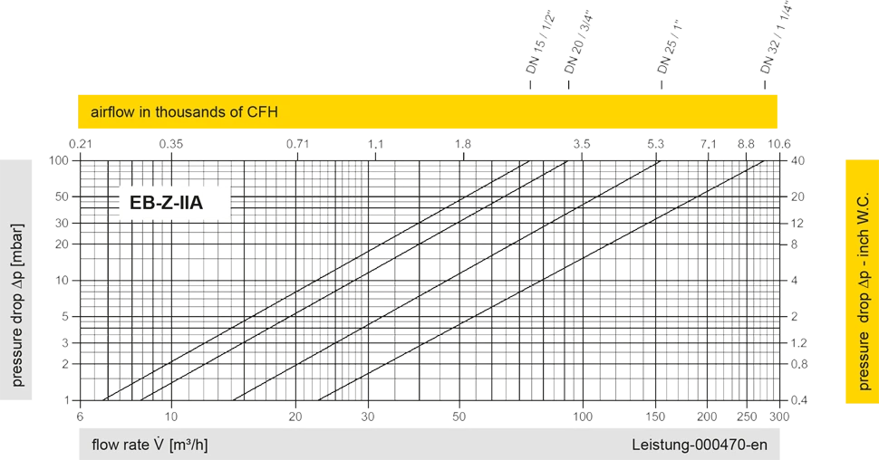
The flow capacity charts have been determined with a calibrated and TÜV certified flow capacity test rig. Volume flow V in (m³/h) and CFH refer to the standard reference conditions of air ISO 6358 (20°C, 1bar). For conversion to other densities and temperatures refer to Sec. 1: “Technical Fundamentals”.