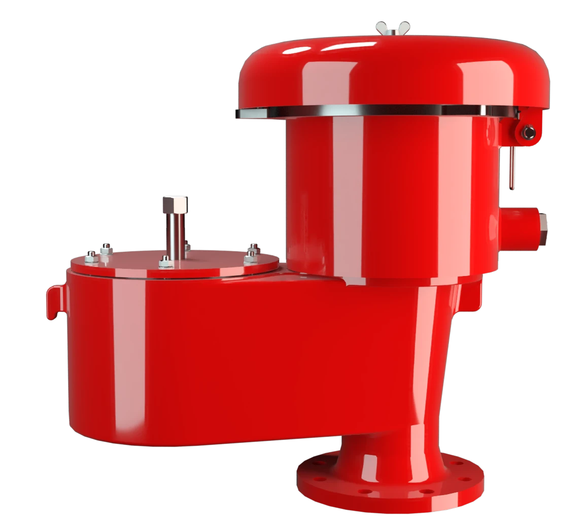
VD/SV-HR
Pressure/Vacuum Relief Valve deflagration- and endurance burning-proof
Features
Extrema estanqueidad
Mantenimiento óptimo de la presión
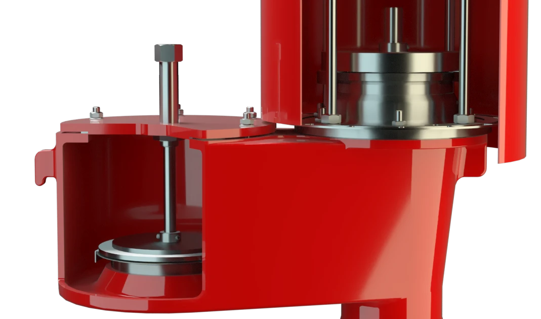
Plato de válvula guiado
Sistema de protección conforme a ATEX
Seguridad contracombustión prolongada
Apagallamas integrado
Diseño modular
Combined Pressure and Vacuum Relief Valve
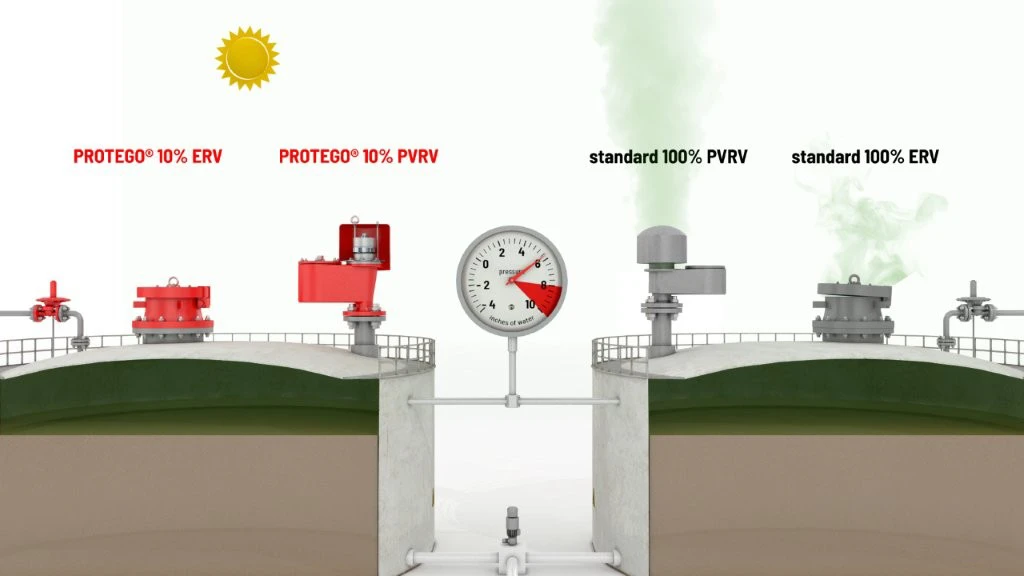
10%-Technology
Advanced Manufacturing Technology
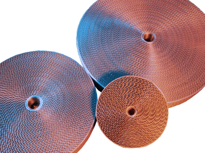
Main Component – PROTEGO® Flame Arrester Unit

Many Individual Certifications
Dimensiones
To select the nominal size (DN), please use the flow capacity charts on the following pages
| DN | 80 / 3" | 100 / 4" |
| a | 500 / 19.69 | 543 / 21.38 |
| b | 477 / 18.78 | 577 / 22.72 |
| c | 353 / 13.90 | 353 / 13.90 |
Dimensiones en mm / pulgadas
Selección del grupo de explosión
| MESG | Expl. Gr. (IEC / CEN) | Gas Group (NEC) |
| > 0,90 mm | IIA | D |
| ≥ 0,65 mm | IIB3 | C |
Special approvals upon request
Selección de materiales para la vivienda
| Design | A | B |
| Housing | Steel | Stainless Steel |
| Valve saets | Stainless Steel | Stainless Steel |
| Gasket | PTFE | PTFE |
| Weather hood | Stainless Steel | Stainless Steel |
| Flame arrester unit | A | A |
Special materials upon request
Combinación de materiales para la unidad apagallamas
| Design | A |
| FLAMEFILTER® cage | Stainless Steel |
| FLAMEFILTER® | Stainless Steel |
Special materials upon request
Selección de materiales para la válvula de presión
| Design | A | B | C | D |
| Pressure range [mbar] [inch W.C.] | +3.5 up to +5.0 +1.4 up to +2.0 | >+5.0 up to +14 >+2.0 up to +5.6 | >+14 up to +35 >+5.6 up to +14 | >+14 up to +35 >+5.6 up to +14 |
| Valve pallet | Aluminium | Stainless Steel | Stainless Steel | Stainless Steel |
| Sealing | FEP | FEP | Metal to Metal | PTFE |
Special material as well as higher set pressure upon request
Selección de materiales para la válvula de vacío
| Design | A | B | C | D |
| Vacuum range [mbar] [inch W.C.] | -2.0 up to -3.5 -0.8 up to -1.4 | <-3.5 up to -14 <-1.4 up to -5.6 | <+14 up to +35 <-5.6 up to -14 | <-14 up to -35 <-5.6 up to -14 |
| Valve pallet | Aluminium | Stainless Steel | Stainless Steel | Stainless Steel |
| Sealing | FEP | FEP | Metal to Metal | PTFE |
Special material as well as higher set vacuum upon request
Tipo de bridas de conexión
| EN 1092-1; Form B1 |
| ASME B16.5 CL 150 R.F. |
other types upon request
Diagrama de flujo volumétrico
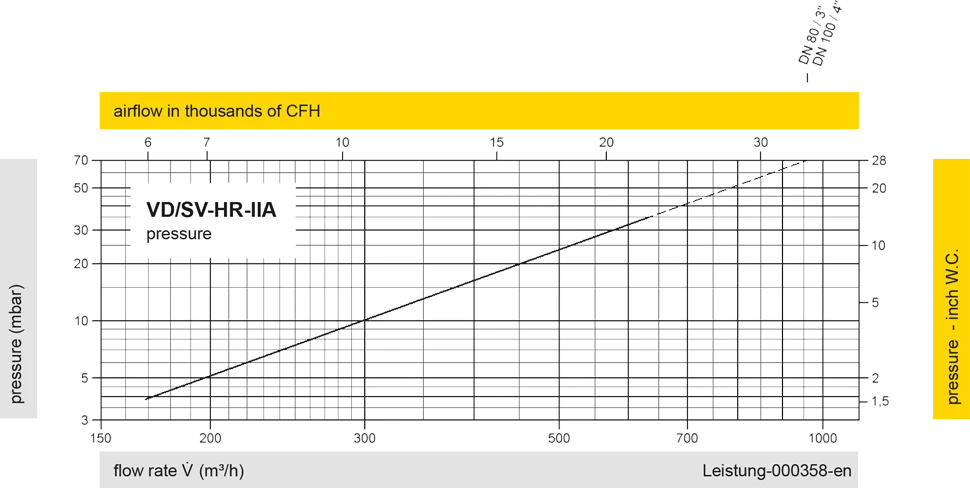
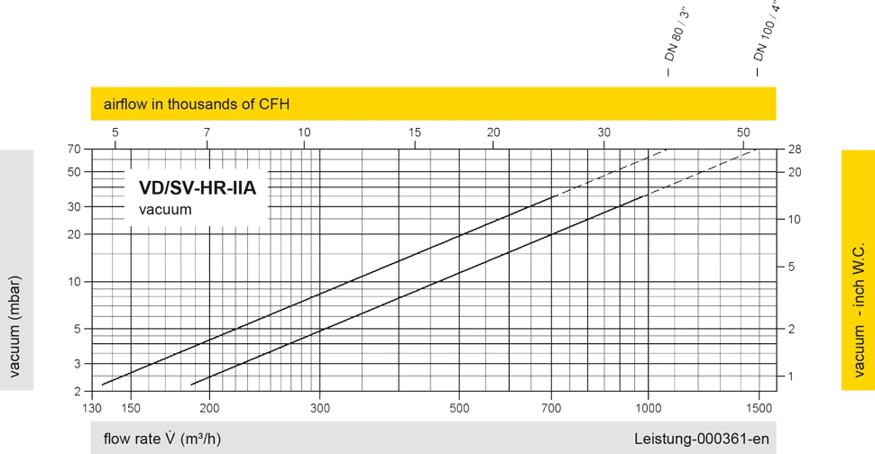
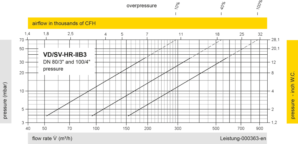
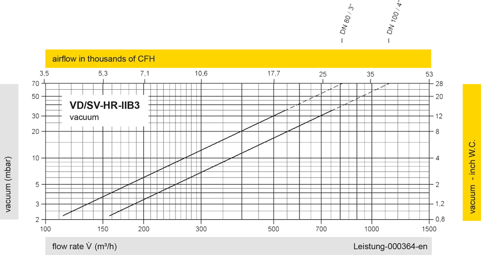
Los diagramas de flujo volumétrico han sido determinados con un banco de pruebas de caudal calibrado y certifi - cado por TÜV. El flujo volumétrico V. en [m³/h] y el CFH se refi eren a las condiciones estándar de referencia de aire según ISO 6358 (20°C, 1bar). La conversión a otras densidades y temperaturas están referidas en el Vol. 1: “Fundamentos Técnicos”.
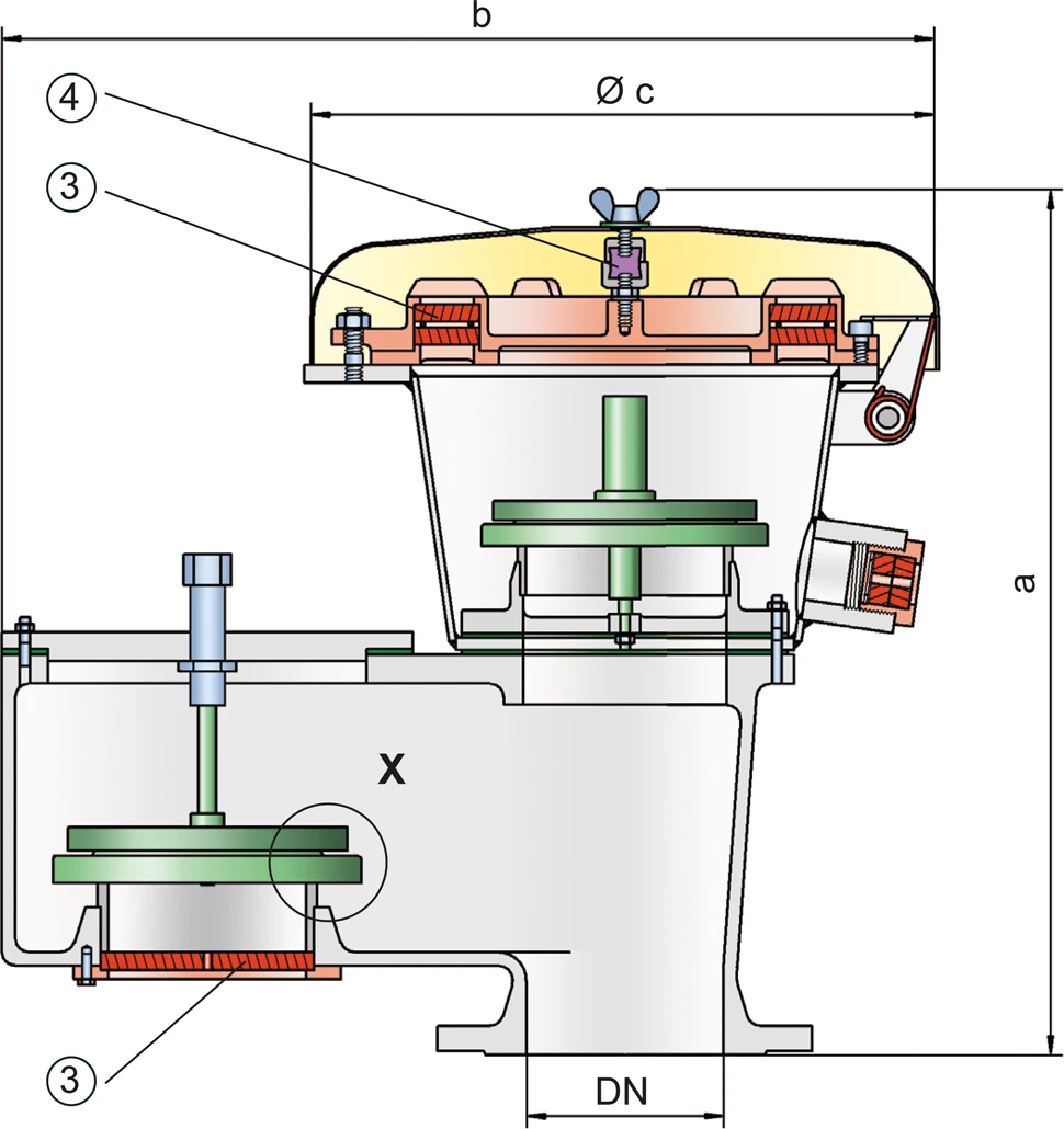
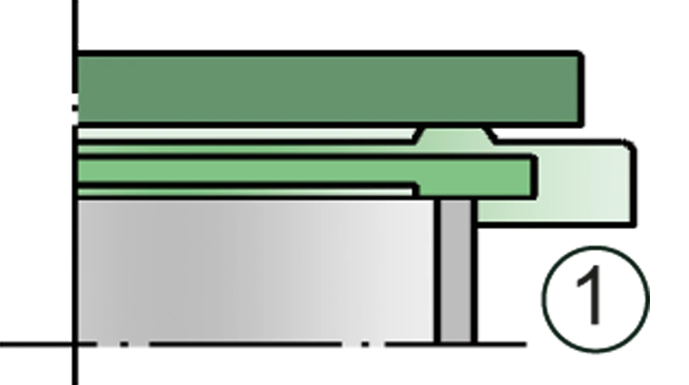
Detail X
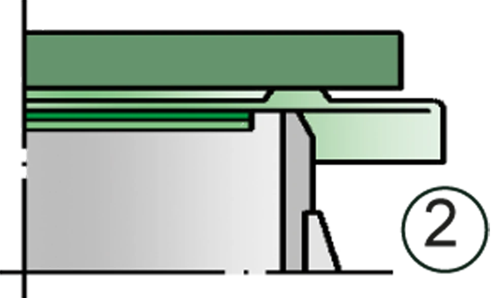
Detail X