ER/VH
Pressure Relief Valve
Features
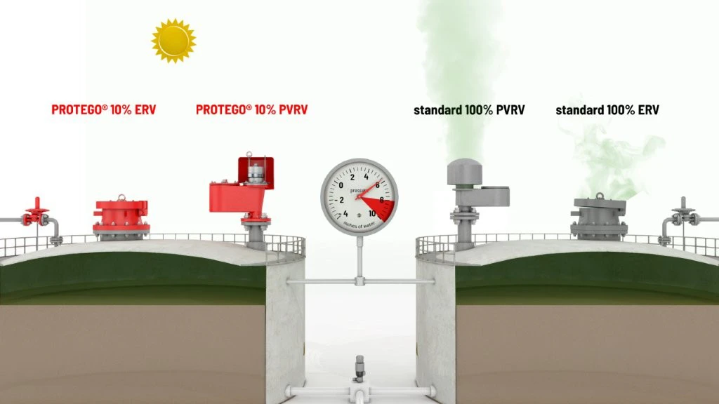
Tecnología del 10%
para un aumento mínimo de presión hasta alcanzar la apertura completa
Extrema estanqueidad
Lo que se traduce en las menores pérdidas posibles de producto y en una reducción de la contaminación ambiental
Mantenimiento óptimo de la presión
Presión de tarado próxima a la presión de apertura para un mantenimiento óptimo de la presión en el sistema
Diseño de cuerpo robusto
(PN 10 & PN 16)
Tapa del cuerpo protegida
Con palanca y contrapeso bloqueable
Tanques API
la mejor tecnología para tanques API
Se usa en zonas con riesgo de explosión
Puede utilizarse en zonas con riesgo de explosión
Flujo volumétrico
Flujo de caudal optimizado
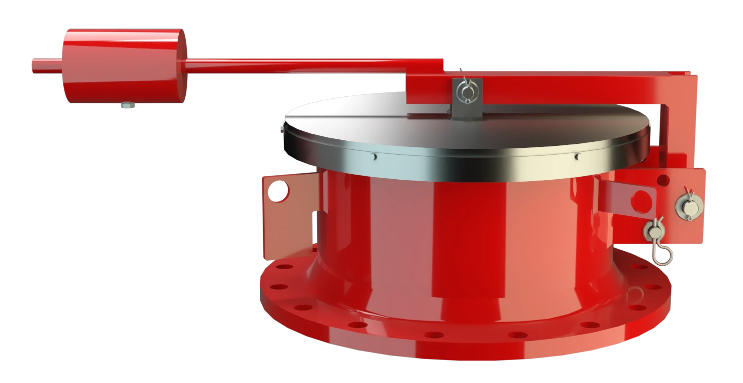
Function and Description
Highly Developed Pressure Relief Valve
The ER/VH Type PROTEGO® valve is a highly developed emergency pressure relief valve with high flow capacity. It is primarily used as a device for emergency pressure relief for storage tanks, containers, silos, and process engineering equipment. It offers reliable protection against overpressure and prevents excessive product vapor loss close to the set pressure. It is designed to release particularly large amounts to prevent the vessel from rupturing in an emergency case. Higher set pressures are achieved by a lever with a lockable weight load. The position of the weight is set at the factory. Starting at DN 500, the devices can also be used as manhole covers.
Patented Valve Pallet Technology
When the set pressure is reached, the valve starts to open and is fully open within 10% overpressure. This unique 10% ”Full Lift Type" technology enables a pressure setting that is only 10% below the maximum allowable working pressure or design pressure of the tank.
Even in the low pressure range, the vent has the opening characteristic comparable to a typical high pressure safety relief valve. The full lift type pallets are a result of many years of development. The valve pallet is mounted on one side.
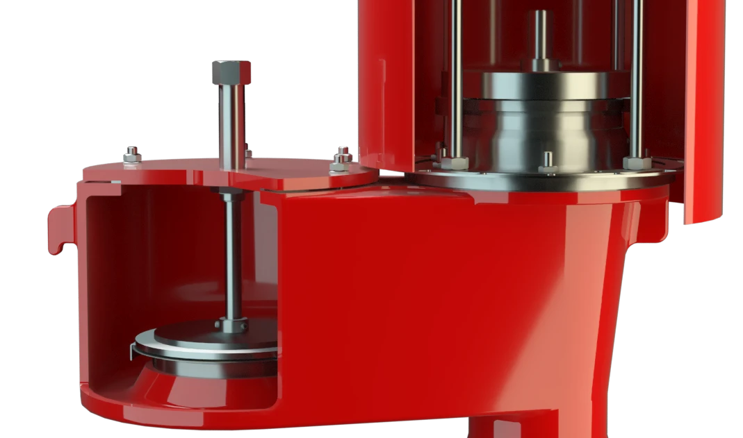
Advanced Manufacturing Technology
Due to the highly developed manufacturing technology, the tank pressure is maintained up to the set pressure with a tightness that is far superior to the conventional standard. This feature is achieved by valve seats made of stainless steel with an inserted O-ring seal, a precisely lapped valve pallet, and a sturdy housing design. After the excess pressure is released, the valve re-seats and provides a tight seal again.
Product Data
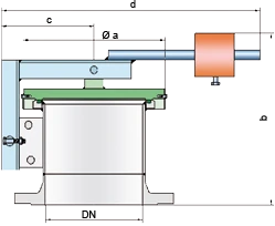
Dimensiones
To select the nominal size (DN), use the flow capacity chart on the following page
| DN | 200 / 8" | 250 / 10" | 300 / 12" | 350 / 14" | 400 / 16" | 450 / 18" | 500 / 20" | 600 / 24" | 700 / 28" |
| a | 305 / 12.01 | 375 / 14.76 | 425 / 16.73 | 445 / 17.52 | 495 / 19.49 | 545 / 21.46 | 615 / 24.21 | 715 / 28.15 | 795 / 31.30 |
| b | 350 / 13.78 | 365 / 14.37 | 385 / 15.16 | 390 / 15.35 | 390 / 15.35 | 415 / 16.34 | 430 / 16.93 | 450 / 17.72 | 465 / 18.31 |
| c | 200 / 7.87 | 240 / 9.45 | 265 / 10.43 | 285 / 11.22 | 310 / 12.20 | 330 / 12.99 | 360 / 14.17 | 410 / 16.14 | 450 / 17.72 |
| d | 590 / 23.23 | 735 / 28.94 | 780 / 30.71 | 845 / 33.27 | 890 / 35.04 | 1070 / 42.13 | 1090 / 42.91 | 1140 / 44.88 | 1380 / 54.33 |
Dimensiones en mm / pulgadas
Selección de materiales
| Design | A | B |
| Housing | Steel | Stainless Steel |
| Valve seat | Stainless Steel | Stainless Steel |
| Valve pallet | Stainless Steel or Steel-Stainless Steel | Stainless Steel |
| Sealing | FPM | FPM |
| Weight | Steel | Stainless Steel |
Special materials upon request
Tipo de bridas de conexión
| EN 1092-1; Form B1 |
| ASME B16.5 CL 150 R.F. |
other types upon request
Diagrama de flujo volumétrico
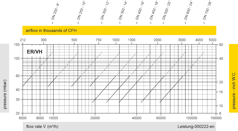
Los diagramas de flujo volumétrico han sido determinados con un banco de pruebas de caudal calibrado y certifi - cado por TÜV. El flujo volumétrico V. en [m³/h] y el CFH se refi eren a las condiciones estándar de referencia de aire según ISO 6358 (20°C, 1bar). La conversión a otras densidades y temperaturas están referidas en el Vol. 1: “Fundamentos Técnicos”.