DR/SV
In-Line Detonation Flame Arrester with shut-off valve, for stable detonations and deflagrations in a straight through design, unidirectional
Features
Fácil mantenimiento
Montaje y desmontaje más rápido
Diseño modular
Seguridad frente a explosiones
Piezas de recambio
Paradas de emergencia
Bombas de vacío
Detonation Arrester With the Advantages of a Shut-Off Valve
Suction-Side Protection for Compressors and Pumps

For Explosion Group IIA
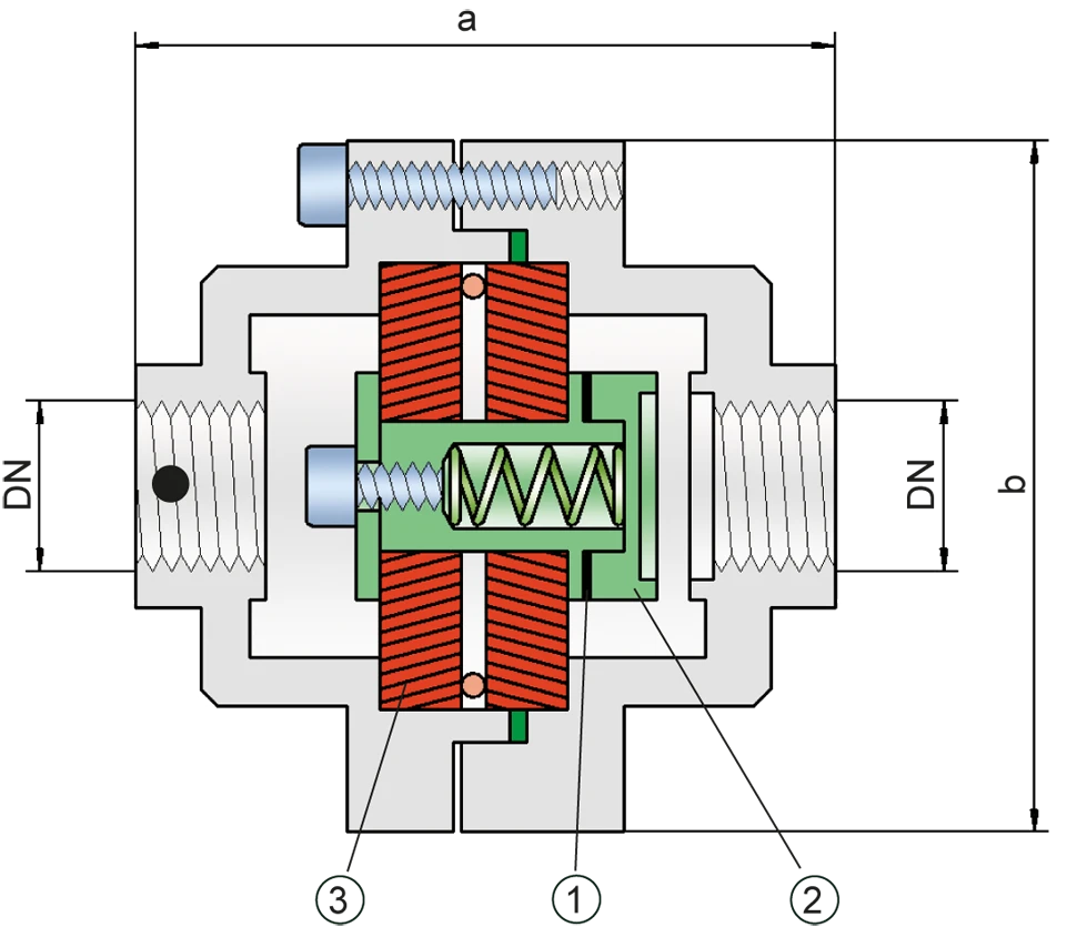
Dimensiones
To select the nominal size (DN), please use the flow capacity chart on the following page
| DN | G ½" | G ¾" |
| a | 115 / 4.53 | 115 / 4.53 |
| b | 100 / 3.94 | 100 / 3.94 |
Dimensiones en mm / pulgadas
Selección del grupo de explosión
| MESG | Expl. Gr. (IEC / CEN) | Gas Group (NEC) |
| > 0,90 mm | IIA | D |
Special approvals upon request
Selección de la máxima presión de operación
| DN | G ½" | G ¾" |
| Pmax | 1,1 / 15.9 | 1,1 / 15.9 |
Pmax = Maximum allowable operating pressure in bar / psi absolut, higher operating pressure upon request
Especificación de la máx. temperatura de operación
| ≤ 60°C / 140°F | Tmaximum allowable operating temperature in °C |
| - | Designation |
higher operating temperatures upon request
Selección de materiales para la vivienda
| Design | A | B |
| Housing | Brass | Stainless Steel |
| Gasket | WS 3822 | WS 3822 |
| Flame arrester unit | A | A, B |
Special materials upon request
Combinación de materiales para la unidad apagallamas
| Design | A | B |
| FLAMEFILTER®* | Stainless Steel | Stainless Steel |
| Spacer | Stainless Steel | Stainless Steel |
| Support for FLAMEFILTER® | Brass | Stainless Steel |
| Washer | Brass | Stainless Steel |
* the FLAMEFILTER® are also available in the materials Tantalum, Inconel, Copper, etc. when the listed housing and cage materials are used.
Special materials upon request
Tipo de conexión
| Pipe thread DIN ISO 228-1 | DIN |
other types of thread upon request
Diagrama de flujo volumétrico
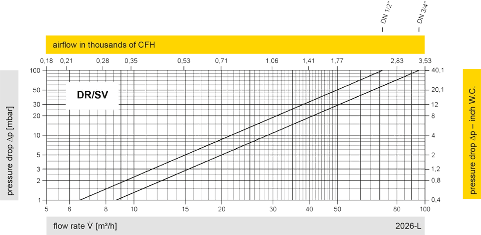
Los diagramas de flujo volumétrico han sido determinados con un banco de pruebas de caudal calibrado y certifi - cado por TÜV. El flujo volumétrico V. en [m³/h] y el CFH se refi eren a las condiciones estándar de referencia de aire según ISO 6358 (20°C, 1bar). La conversión a otras densidades y temperaturas están referidas en el Vol. 1: “Fundamentos Técnicos”.