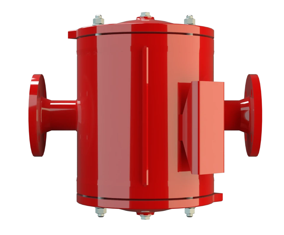
DR/SBW
In-Line Detonation Flame Arrester for stable detonations and deflagrations in a straight through design with shock absorber, bidirectional
Features
Fácil mantenimiento
Número reducido de discos FLAMEFILTER®
Diseño modular
Transmisión bidireccional de la llama
Amplio rango de aplicaciones
Posibilidad de instalar sensores de temperatura
Piezas de recambio
Bajo coste
Maintenance-Friendly In-Line-Detonation Flame Arrester
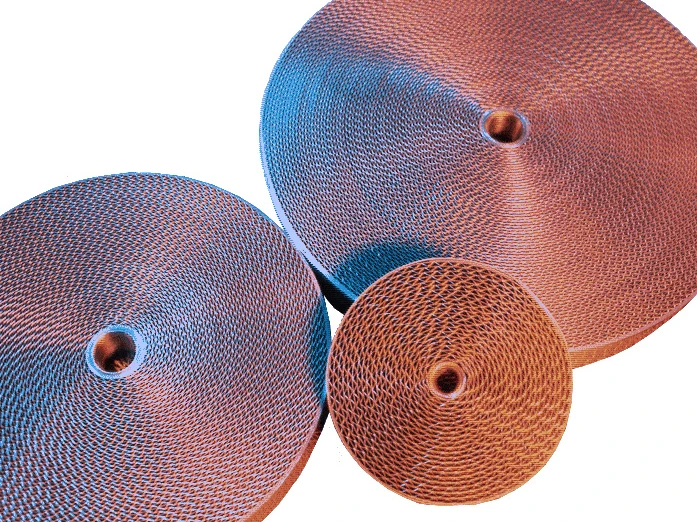
Main Component – PROTEGO® Flame Arrester Unit

Many Individual Certifications
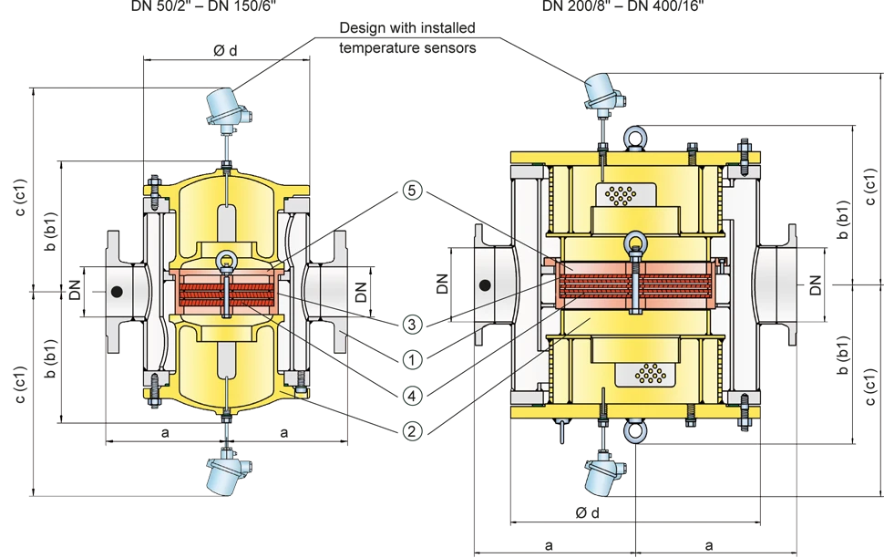
Dimensiones
To select the nominal size (DN) and nominal width (NG), please use the flow capacity charts on the following pages
| DN | 50 / 2" | 80 / 3" | 100 / 4" | 150 / 6" | 200 / 8" | 250 / 10" | 300 / 12" | 350 / 14" | 400 / 16" |
| NG | 150 / 6" | 150 / 6" | 200 / 8" | 300 / 12" | 500 / 20" | 500 / 20" | 600 / 24" | 700 / 28" | 800 / 32" |
| a | 225 / 8.86 | 225 / 8.86 | 275 / 10.83 | 350 / 13.78 | 550 / 21.65 | 550 / 21.65 | 725 / 28.54 | 800 / 31.50 | 825 / 32.48 |
| b | 210 / 8.27 | 210 / 8.27 | 220 / 8.66 | 290 / 11.42 | 525 / 20.67 | 525 / 20.67 | 590 / 23.23 | 655 / 25.78 | 725 / 28.54 |
| b1* | 325 / 12.80 | 325 / 12.80 | 360 / 14.17 | 475 / 18.70 | 835 / 32.87 | 835 / 32.87 | 960 / 37.80 | 1075 / 42.32 | 1215 / 47.83 |
| c | 395 / 15.55 | 395 / 15.55 | 410 / 16.14 | 475 / 18.70 | 630 / 24.80 | 630 / 24.80 | 700 / 27.56 | 765 / 30.12 | 835 / 32.87 |
| c1* | 450 / 17.72 | 450 / 17.72 | 465 / 18.31 | 530 / 20.87 | 730 / 28.74 | 730 / 28.74 | 800 / 31.50 | 865 / 34.06 | 935 / 36.81 |
| d | 275 / 10.83 | 275 / 10.83 | 325 / 12.80 | 460 / 18.11 | 840 / 33.07 | 840 / 33.07 | 1000 / 39.37 | 1150 / 45.28 | 1250 / 49.21 |
Dimensiones en mm / pulgadas
* b1 dismantling dimension for servicing
c1 dismantling dimension for servicing (temperature sensor)
Selección del grupo de explosión
| MESG | Expl. Gr. (IEC / CEN) | Gas Group (NEC) |
| > 0,90 mm | IIA | D |
| ≥ 0,65 mm | IIB3 | C |
Special approvals upon request
Selección de la máxima presión de operación
| DN | 50 / 2" | 80 / 3" | 100 / 4" | 150 / 6" | 200 / 8" | 250 / 10" | 300 / 12" | 350 / 14" | 400 / 16" | ||
| NG | 150 / 6" | 150 / 6" | 200 / 8" | 300 / 12" | 500 / 20" | 500 / 20" | 600 / 24" | 700 / 28" | 800 / 32" | ||
| Expl. Gr. | IIA | Pmax | 4 / 58 | 4 / 58 | 3 / 43.5 | 3 / 43.5 | 1.6 / 23.2 | 1.6 / 23.2 | 1.1 / 15.9 | 1.1 / 15.9 | 1.1 / 15.9 |
| Expl. Gr. | IIB3 | Pmax | 1.7 / 24.6 | 1.7 / 24.6 | 1.7 / 24.6 | 1.7 / 24.6 | 1.2 / 17.4 | 1.2 / 17.4 | 1.1 / 15.9 | 1.1 / 15.9 | 1.1 / 15.9 |
Pmax = Maximum allowable operating pressure in bar / psi absolut, higher operating pressure upon request
Especificación de la máx. temperatura de operación
| ≤ 60°C / 140°F | Tmaximum allowable operating temperature in °C |
| - | Designation |
higher operating temperatures upon request
Selección de materiales para la vivienda
| Design | A | B | C |
| Housing | Steel | Stainless Steel | Hastelloy |
| Heating jacket (DR / SBW-H-(T)-...) | Steel | Stainless Steel | Stainless Steel |
| Cover with shock absorber | Steel | Stainless Steel | Hastelloy |
| Gasket | FPM* | PTFE | PTFE |
| Flame arrester unit | A | C, D | E |
* for devices exposed to elevated temperatures above 150°C / 302 °F (T150), gaskets made of PTFE. Special device with unidirectional shock absorber DR/SW-... from DN 50 resp. NG 150 available.
Special materials upon request
Combinación de materiales para la unidad apagallamas
| Design | A | C | D | E |
| FLAMEFILTER® cage | Steel | Stainless Steel | Stainless Steel | Hastelloy |
| FLAMEFILTER®* | Stainless Steel | Stainless Steel | Hastelloy | Hastelloy |
| Spacer | Stainless Steel | Stainless Steel | Hastelloy | Hastelloy |
* the FLAMEFILTER® are also available in the materials Tantalum, Inconel, Copper, etc. when the listed housing and cage materials are used.
Special materials upon request
Tipo de bridas de conexión
| EN 1092-1; Form B1 |
| ASME B16.5 CL 150 R.F. |
other connections upon request
Diagrama de flujo volumétrico
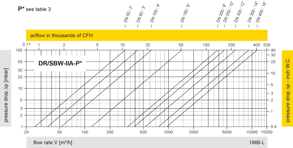
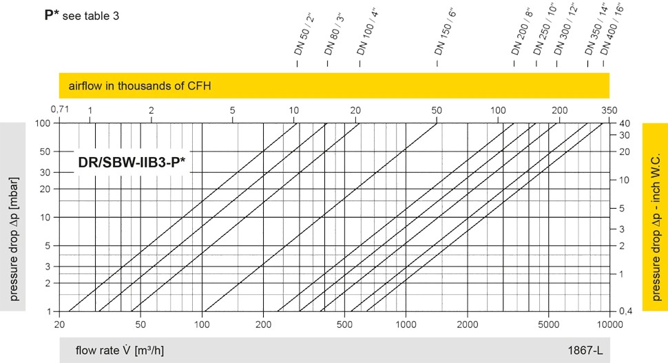
Los diagramas de flujo volumétrico han sido determinados con un banco de pruebas de caudal calibrado y certifi - cado por TÜV. El flujo volumétrico V. en [m³/h] y el CFH se refi eren a las condiciones estándar de referencia de aire según ISO 6358 (20°C, 1bar). La conversión a otras densidades y temperaturas están referidas en el Vol. 1: “Fundamentos Técnicos”.