PM/(D)S
Pressure/Vacuum Relief Valve Pilot-operated diaphragm valve
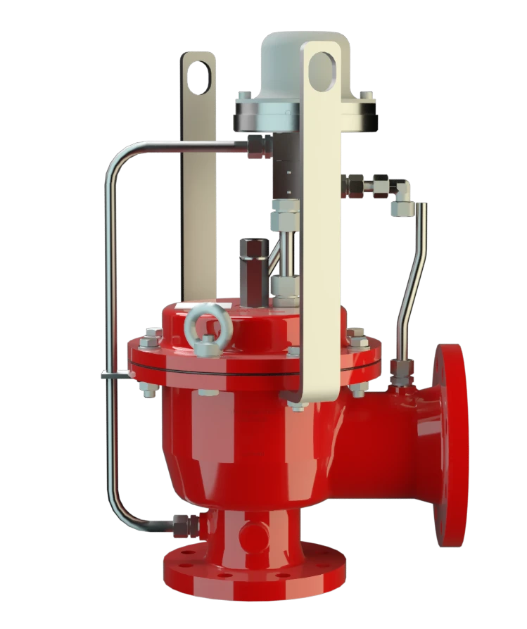
Features
Alto nivel de seguridad
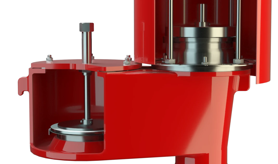
Imanes permanentes
Característica de apertura rápida
Extrema estanqueidad
Mantenimiento óptimo de la presión
Flujo volumétrico
Se usa en zonas con riesgo de explosión
Baja temperatura
Drenaje de condensados
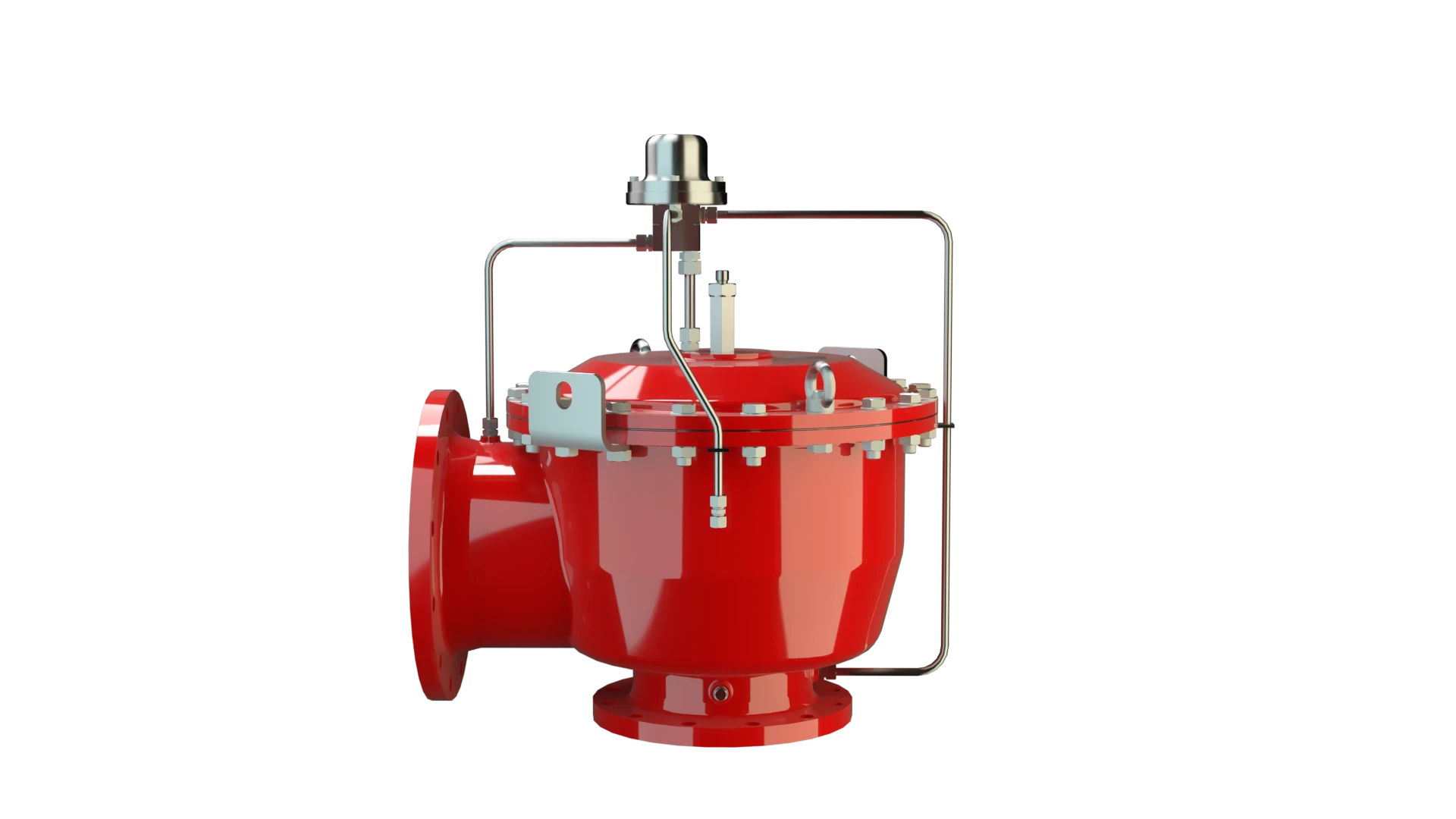
Combined Pressure and Vacuum Relief Valve
Corrosion-Resistant and Cryogenic Permanent Magnet
Advanced Manufacturing Technology
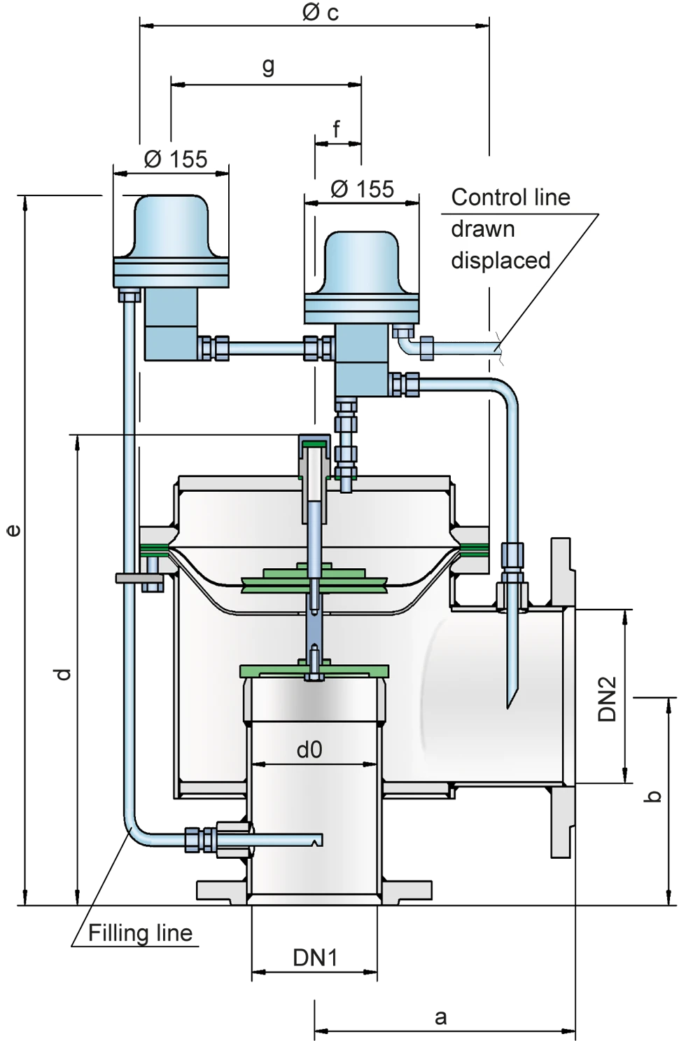
Dimensiones
To select the nominal size Diamètre nominal The nominal size is an alphanumeric designation of size for components in a piping system, used for reference purposes, comprising the letters DN followed by a dimensionless integer that is indirectly related to the physical size of the bore or outside diameter of the connections, expessed in millimeters. (DN), use the flow capacity charts on the following pages
| DN1 | 80 / 3" | 100 / 4" | 150 / 6" | 200 / 8" | 250 / 10" | 300 / 12 | 300 / 12" |
| DN2 | 100 / 4" | 150 / 6" | 200 / 8" | 250 / 10" | 300 / 12" | 350 / 14" | 400 |
| a | 225 / 8.86 | 250 / 9.87 | 325 / 12.80 | 375 / 14.76 | 450 / 17.72 | 500 / 19.69 | 500 / 19.69 |
| b | 150 / 5.91 | 175 / 6.89 | 225 / 8.86 | 250 / 9.84 | 270 / 10.63 | 300 / 11.81 | 325 / 12.79 |
| c | 275 / 10.83 | 330 / 12.99 | 445 / 17.52 | 550 / 21.65 | 665 / 26.18 | 785 / 30.91 | 785 / 30.91 |
| d | 370 / 14.57 | 425 / 16.73 | 530 / 20.87 | 605 / 23.82 | 675 / 26.57 | 785 / 30.91 | 835 / 32.87 |
| e | 615 / 24.21 | 685 / 26.97 | 770 / 30.31 | 825 / 32.48 | 935 / 36.81 | 1005 / 39.57 | 1055 / 41.53 |
| f | 35 / 1.38 | 40 / 1.57 | 40 / 1.57 | 50 / 1.97 | 50 / 1.97 | 50 / 1.97 | 50 / 1.97 |
| g | 160 / 6.30 | 195 / 7.68 | 250 / 9.84 | 315 / 12.40 | 370 / 14.57 | 425 / 16.73 | 425 / 16.73 |
Dimensiones en mm / pulgadas
Selección de materiales para la vivienda
| Design | A | B |
| Housing | Aluminium | Stainless Steel |
| Valve seat | Stainless Steel | Stainless Steel |
| Sealing | KL-C-4106 | KL-C-4106 |
| Main diaphragm protection | Stainless Steel | Stainless Steel |
| Pilot lines | Stainless Steel | Stainless Steel |
| Pilot housing Corps A housing is a solid shell, which surrounds a content, either protecting the content from external influences, or protecting the environment from the content. | Stainless Steel | Stainless Steel |
| Pilot diaphragm | FEP | FEP |
Special materials upon request
Material selection for valve pallet
| Design | A | B | C |
| Pressure range [mbar] [inch W.C.] | -3,0 up to -4* -1.2 up to -1.6* | -4,0 up to -5,0* -1.6 upm to -2.0* | -5,0 up to -7,0* -2.0 up to -2,8* |
| Valve pallet | Aluminium | Stainless Steel | Stainless Steel |
| Diaphragm | FEP | FEP | FEP |
| Diaphragm pallet | Aluminium | Aluminium | Stainless Steel |
* The indicated vacuum ranges depend on the nominal size and can differ. The pressure Setting can be combined with any vacuum setting
Special materials upon request
Tipo de bridas de conexión
| EN 1092-1; Form B1 |
| ASME B16.5 CL 150 R.F. |
other types upon request
Diagrama de flujo volumétrico
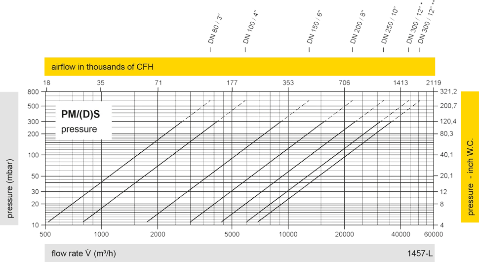
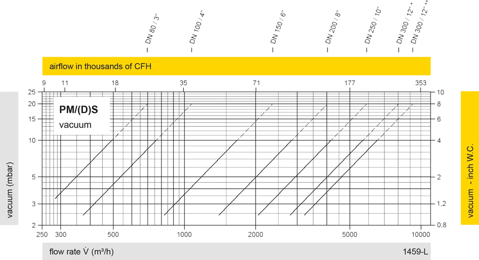
Los diagramas de flujo volumétrico han sido determinados con un banco de pruebas de caudal calibrado y certifi - cado por TÜV. El flujo volumétrico V. en [m³/h] y el CFH se refi eren a las condiciones estándar de referencia de aire según ISO 6358 (20°C, 1bar). La conversión a otras densidades y temperaturas están referidas en el Vol. 1: “Fundamentos Técnicos”.
 PROTEGO®
 Representative
 PARC / Service Partner