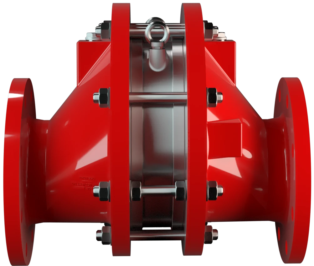
FA-E-IIA1
In-Line Deflagration Flame Arrester for biogas, sewage gas and landfill gas, eccentric design, bidirectional, endurance burning proof (under atmospheric conditions up to DN 200 / 8“)
Features
Diseño excéntrico
Opciones de aplicación versátiles
Diseño modular
Montaje y desmontaje más rápido
Proporciona seguridad
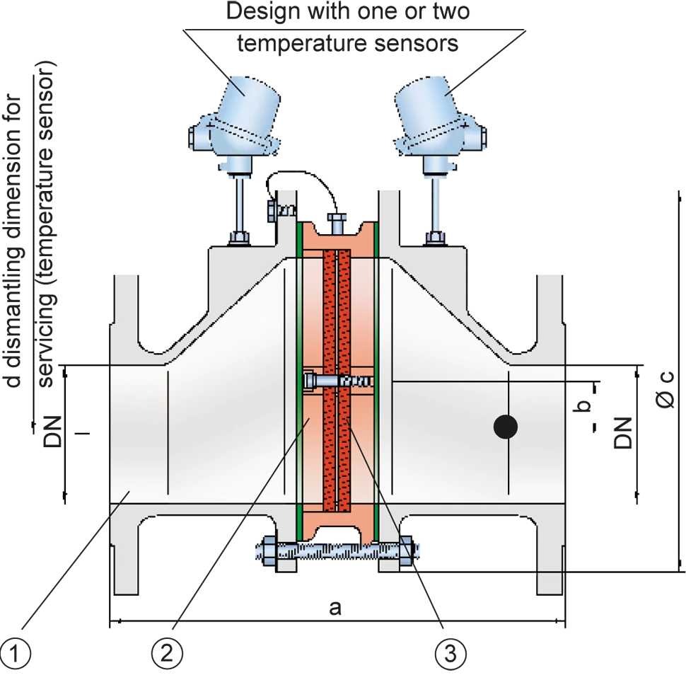
Posibilidad de instalar sensores de temperatura
Piezas de recambio
Excentric Design
For Explosion Group IIA1
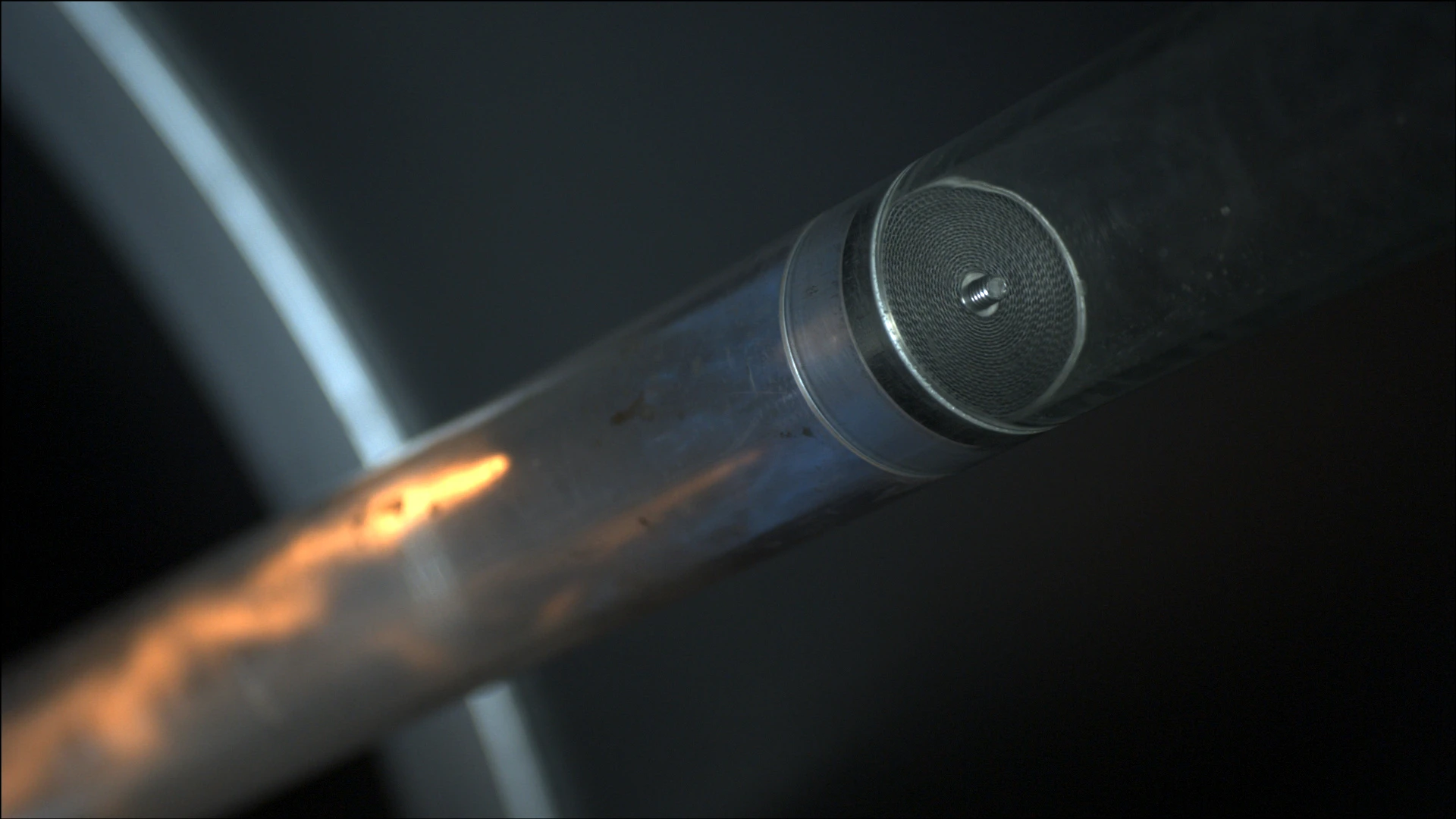
Main Component – PROTEGO® Flame Arrester Unit

Many Individual Certifications
Dimensiones
To select the nominal size Diamètre nominal The nominal size is an alphanumeric designation of size for components in a piping system, used for reference purposes, comprising the letters DN followed by a dimensionless integer that is indirectly related to the physical size of the bore or outside diameter of the connections, expessed in millimeters. (DN), please use the flow capacity charts on the following pages
| DN | 25 / 1" | 32 / 1¼" | 40 / 1½" | 50 / 2" | 65 / 2½" | 80 / 3" | 100 / 4" | 125 / 5" | 150 / 6" | 200 / 8" | 250 / 10" | 300 / 12" |
| a | 304 / 11.97 | 304 / 11.97 | 310 / 12.20 | 314 / 12.36 | 360 / 14.17 | 364 / 14.33 | 370 / 14.57 | 435 / 17.09 | 440 / 17.32 | 450 / 17.72 | 480 / 18.90 | 500 / 16.69 |
| b | 29 / 1.14 | 29 / 1.14 | 29 / 1.14 | 29 / 1.14 | 38 / 1.49 | 38 / 1.49 | 39 / 1.53 | 65 / 2.56 | 65 / 2.56 | 55 / 2.17 | 58 / 2.28 | 60 / 2.36 |
| c | 185 / 7.28 | 185 / 7.28 | 210 / 8.27 | 210 / 8.27 | 250 / 9.84 | 250 / 9.84 | 275 / 10.83 | 385 / 15.16 | 385 / 15.16 | 450 / 17.72 | 500 / 19.69 | 575 / 22.64 |
| d | 400 / 15.75 | 400 / 15.75 | 410 / 16.14 | 410 / 16.14 | 440 / 16.14 | 440 / 16.14 | 460 / 18.11 | 520 / 20.47 | 520 / 20.47 | 540 / 21.26 | 570 / 22.44 | 600 / 23.62 |
Dimensiones en mm / pulgadas
Selección del grupo de explosión
| MESG | Expl. Gr. (IEC / CEN) |
| ≥ 1.14 mm | IIA1 (I)* |
* former designation Expl.gr. I
Special approvals upon request
Selección de la máxima presión de operación
| Expl.Gr. | DN | 25 / 1" | 32 / 1¼" | 40 / 1½" | 50 / 2" | 65 / 2½" | 80 / 3" | 100 / 4" | 125 / 5" | 150 / 6" | 200 / 8" | 250 / 10" | 300 / 12" |
| IIA1 (I) | Pmax | 1,9 / 27.5 | 1,9 / 27.5 | 1,9 / 27.5 | 1,9 / 27.5 | 1,9 / 27.5 | 1,9 / 27.5 | 1,9 / 27.5 | 1,9 / 27.5 | 1,9 / 27.5 | 1,9 / 27.5 | 1,9 / 27.5 | 1,9 / 27.5 |
Pmax = Maximum allowable operating pressure in bar / psi absolut, higher operating pressure upon request
Especificación de la máx. temperatura de operación
| ≤ 60°C / 140°F | Tmaximum allowable operating temperature in °C |
| - | Designation |
higher operating temperatures upon request
Selección de materiales para la vivienda
| Design | B | C | |
| Housing | Steel | Stainless Steel | |
| Gasket | PTFE | PTFE | |
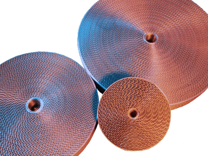
| Flame arrester unit Flame arrester unit Flame arrester casing with FLAMEFILTER® set. | A, B | B |
* for devices exposed to elevated temperatures above 150°C / 302°F (T150), gaskets made of PTFE.
The housing can also be delivered in carbon steel with an ECTFE coating Revêtement Coating is the application of a firmly adhering layer of shapeless material to the surface of a workpiece. . Special materials upon request.
Combinación de materiales para la unidad apagallamas
| Design | A | B |
| FLAMEFILTER® cage | Steel | Stainless Steel |
| FLAMEFILTER®* | Stainless Steel | Stainless Steel |
| Spacers | Stainless Steel | Stainless Steel |
*the FLAMEFILTER® is also available in the materials Tantalum, Inconel, Copper, etc. when the listed housing and cage materials are used.
Special materials upon request.
Tipo de bridas de conexión
| EN 1092-1; Form B1 |
| ASME B16.5 CL 150 R.F. |
other connections upon request
Diagrama de flujo volumétrico
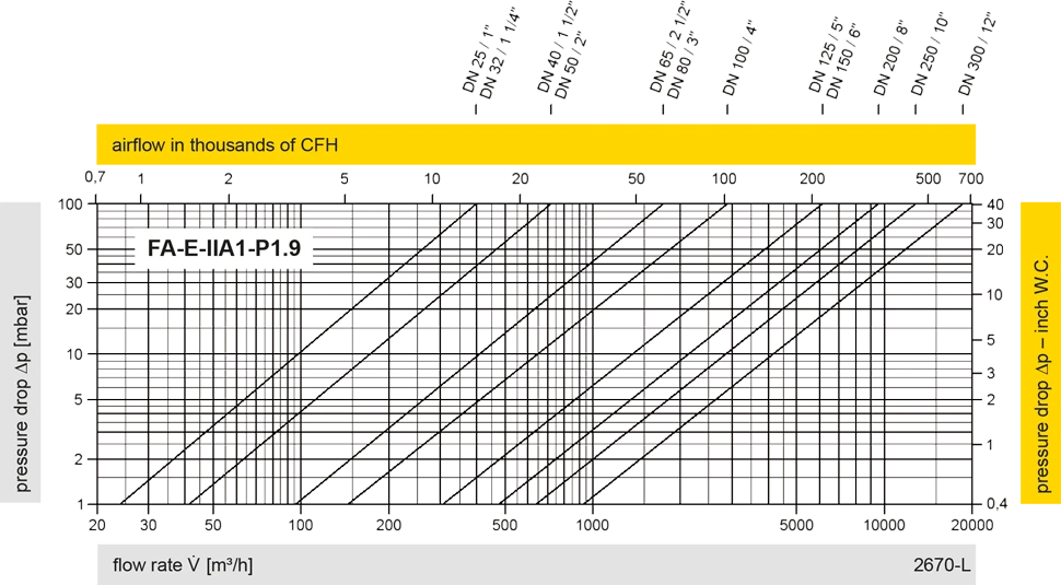
Los diagramas de flujo volumétrico han sido determinados con un banco de pruebas de caudal calibrado y certifi - cado por TÜV. El flujo volumétrico V. en [m³/h] y el CFH se refi eren a las condiciones estándar de referencia de aire según ISO 6358 (20°C, 1bar). La conversión a otras densidades y temperaturas están referidas en el Vol. 1: “Fundamentos Técnicos”.


 PROTEGO®
 Representative
 PARC / Service Partner