Features
La caperuza proporciona protección
Dispositivo eficiente en coste
Curvas de caudal certificadas
Prácticamente libre de mantenimiento
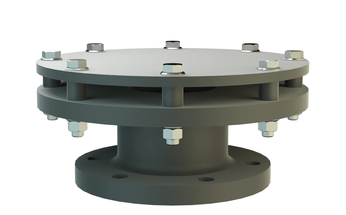
In- and Out-Breathing – for use with Aggressive Products
Protective Cover for Preventing Flame Transmission
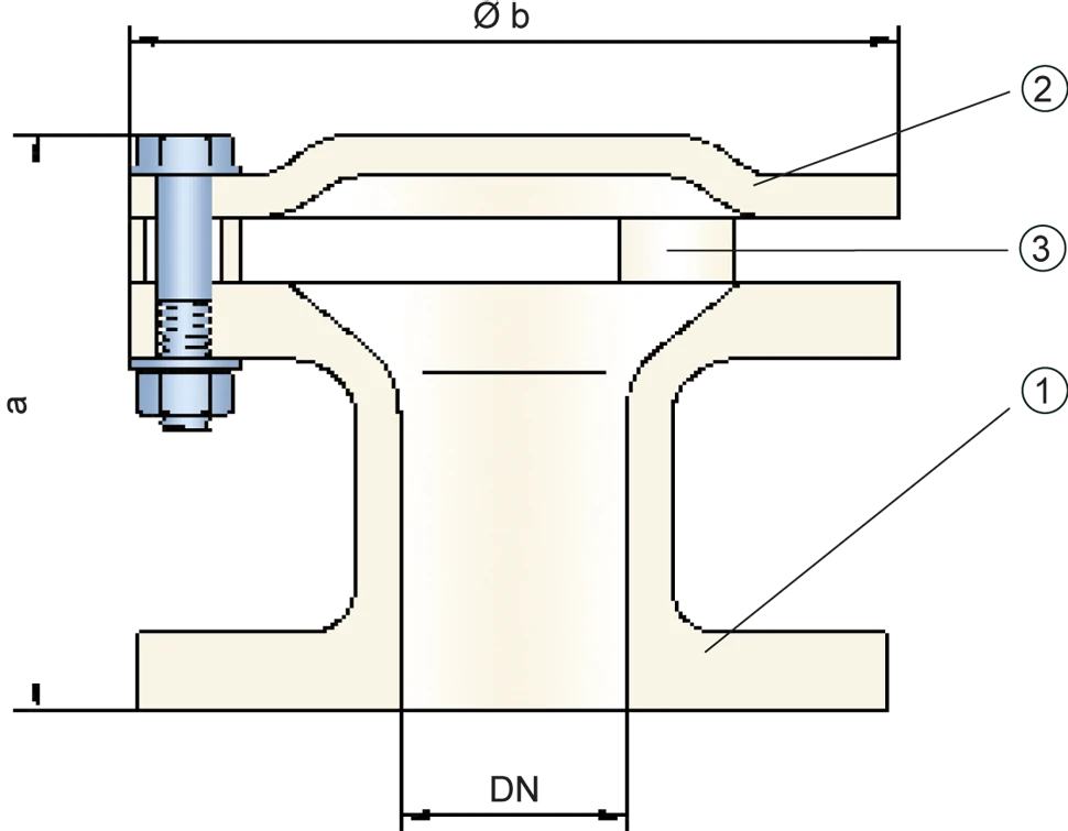
Dimensiones
To select the nominal size Diamètre nominal The nominal size is an alphanumeric designation of size for components in a piping system, used for reference purposes, comprising the letters DN followed by a dimensionless integer that is indirectly related to the physical size of the bore or outside diameter of the connections, expessed in millimeters. (DN), please use the flow capacity charts on the following pages
| DN | 50 / 2" | 80 / 3" | 100 / 4" | 150 / 6" | 200 / 8" |
| a | 135 / 5.31 | 140 / 5.51 | 145 / 5.71 | 195 / 7.68 | 200 / 7.87 |
| b | 170 / 6.69 | 230 / 9.06 | 300 / 11.81 | 375 / 14.76 | 450 / 17.72 |
Dimensiones en mm / pulgadas
Selección de materiales
| Design | A | B | C |
| Housing | PE | PP | PVDF |
| Weather hood | PE | PP | PVDF |
Special materials upon request
Tipo de bridas de conexión
| EN 1092-1; Form B1 |
| ASME B16.5 CL 150 R.F. |
other types upon request
Diagrama de flujo volumétrico
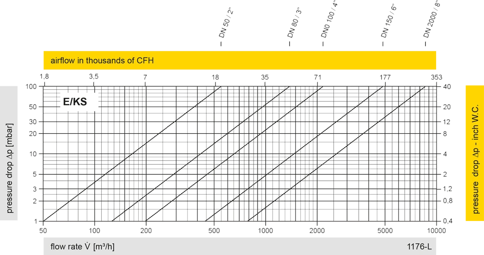
Los diagramas de flujo volumétrico han sido determinados con un banco de pruebas de caudal calibrado y certifi - cado por TÜV. El flujo volumétrico V. en [m³/h] y el CFH se refi eren a las condiciones estándar de referencia de aire según ISO 6358 (20°C, 1bar). La conversión a otras densidades y temperaturas están referidas en el Vol. 1: “Fundamentos Técnicos”.


 PROTEGO®
 Representative
 PARC / Service Partner