Features
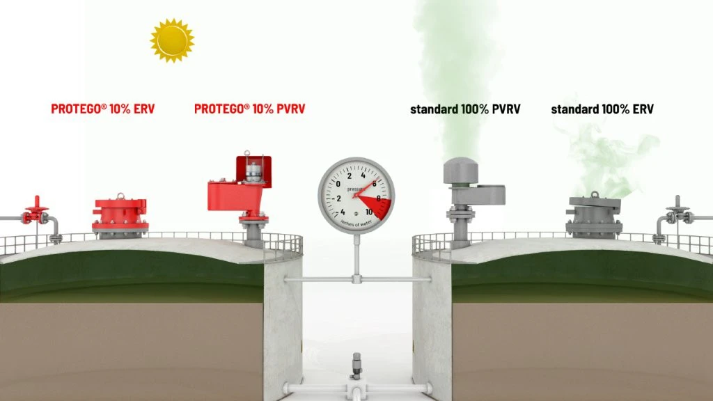
Tecnología del 10%
Extrema estanqueidad
Mantenimiento óptimo de la presión
Alta capacidad volumétrica
Conexiones independientes
Se usa en zonas con riesgo de explosión
Diseño de cuerpo robusto
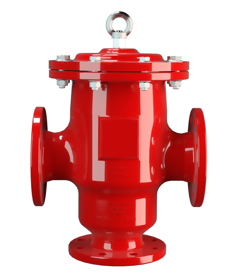
Pressure and Vacuum Relief Valve with Separate Connections for Pressure and Vacuum Breathing
Full Lift Technology
Advanced Manufacturing Technology
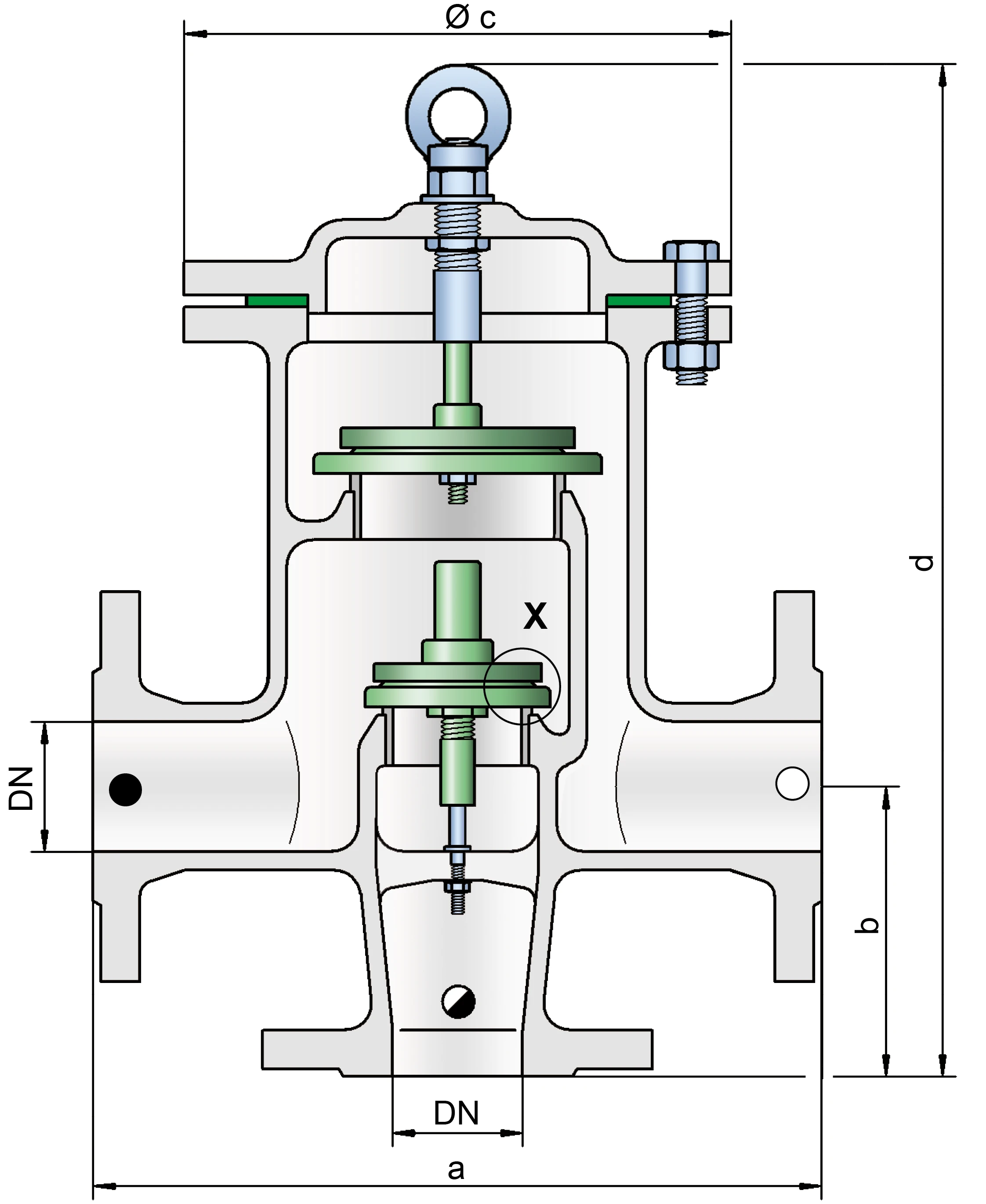
Dimensiones
To select the nominal size Diamètre nominal The nominal size is an alphanumeric designation of size for components in a piping system, used for reference purposes, comprising the letters DN followed by a dimensionless integer that is indirectly related to the physical size of the bore or outside diameter of the connections, expessed in millimeters. (DN), please use the flow capacity charts on the following pages
| DN | 40 / 1½" | 50 / 2" | 65 / 2½" | 80 / 3" | 100 / 4" | 150 / 6" |
| a | 280 / 11.02 | 280 / 11.02 | 340 / 13.39 | 340 / 13.39 | 390 / 15.35 | 520 / 20.47 |
| b | 165 / 6.50 | 165 / 6.50 | 200 / 7.84 | 200 / 7.84 | 240 / 9.45 | 300 / 11.81 |
| c | 210 / 8.27 | 210 / 8.27 | 280 / 11.02 | 280 / 11.02 | 310 / 12.20 | 390 / 15.35 |
| d | 440 / 17.32 | 440 / 17.32 | 495 / 19.49 | 495 / 19.49 | 590 / 23.23 | 715 / 28.15 |
Dimensiones en mm / pulgadas
Larger sizes upon request
Dimensions for pressure and vacuum relief valve Soupape de surpression et dépression A pressure and vacuum relief valve is a pressure equalization valve for impermissible pressure and vacuum in a closed system. with heating jacket upon request
Selección de materiales para la vivienda
| Design | A | B |
| Housing | Steel | Stainless Steel |
| Heating jacket (DV / ZU-H-...) | Steel | Stainless Steel |
| Valve seat | Stainless Steel | Stainless Steel |
| Gasket | PTFE | PTFE |
Option: Housing with ECTFE-lining
Special materials upon request
Selección de materiales para la válvula de presión
| Design | A | B | C | D |
| Pressure range [mbar] [inch W.C.] | +2.0up to +3.5 +0.8up to +1.4 | >+3.5up to +14 >+1.4 up to +5.6 | >+14up to +60 >+5.6up to +24 | >+14up to +60 >+5.6up to +24 |
| Valve pallet | Aluminium | Stainless Steel | Stainless Steel | Stainless Steel |
| Sealing | FEP | FEP | Metal to Metal | PTFE |
Special materials upon request
For higher set pressures refer to type DV/ZU-F.
Selección de materiales para la válvula de vacío
| Design | A | B | C | D | E | F |
| Pressure range [mbar] [inch W.C.] | -3.5up to -5.0 -1.4up to -2.0 | <-5.0 up to -14 <-2.0up to -5.6 | <-14up to -35 <-5.6 up to -14 | <-35 up to -50 <-14 up to -20 | <-14 up to -35 <-5.6 up to -14 | <-35 up to -50 <-14 up to -20 |
| Valve pallet | Aluminium | Stainless Steel | Stainless Steel | Stainless Steel | Stainless Steel | Stainless Steel |
| Sealing | FEP | FEP | Metal to Metal | Metal to Metal | PTFE | PTFE |
Special materials and lower set vacuum upon request.
Tipo de bridas de conexión
| EN 1092-1; Form B1 |
| ASME B16.5 CL 150 R.F. |
other types upon request
Diagrama de flujo volumétrico

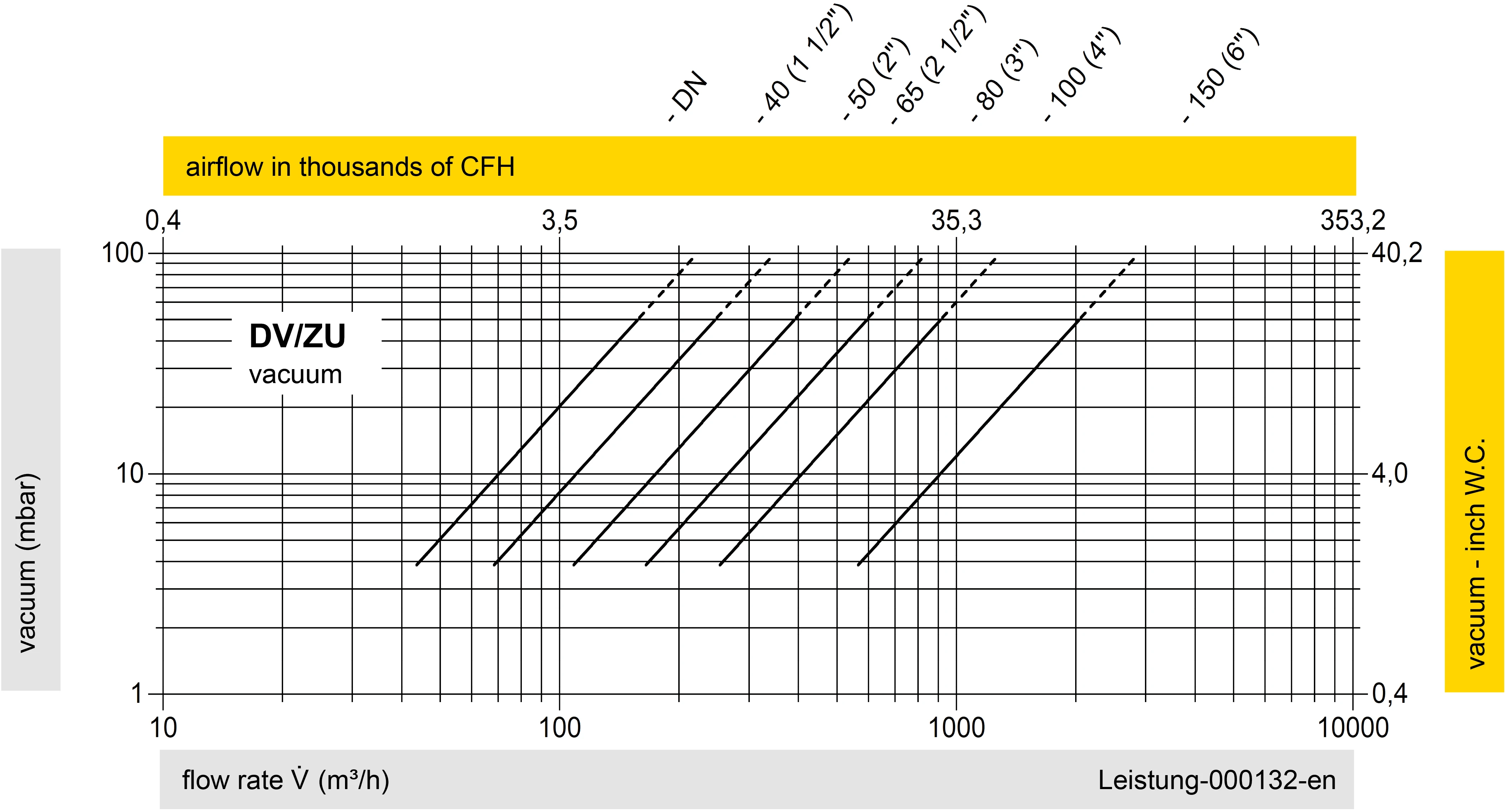
Los diagramas de flujo volumétrico han sido determinados con un banco de pruebas de caudal calibrado y certifi - cado por TÜV. El flujo volumétrico V. en [m³/h] y el CFH se refi eren a las condiciones estándar de referencia de aire según ISO 6358 (20°C, 1bar). La conversión a otras densidades y temperaturas están referidas en el Vol. 1: “Fundamentos Técnicos”.
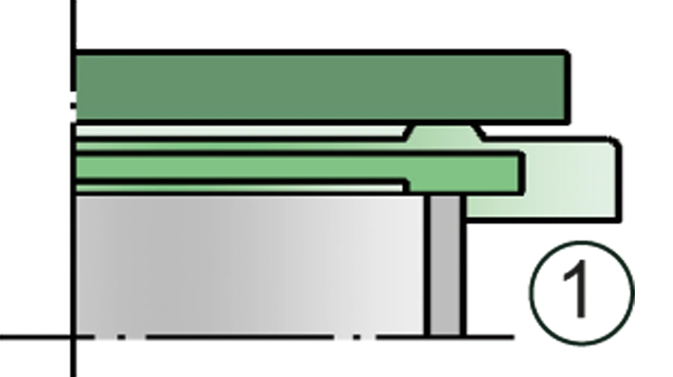
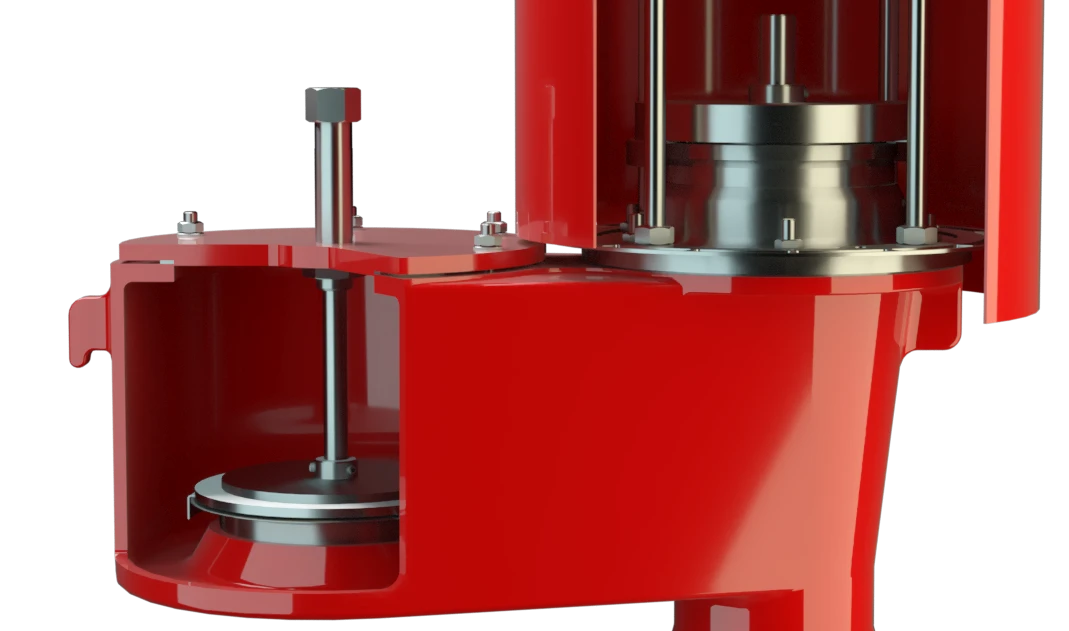
Detail X
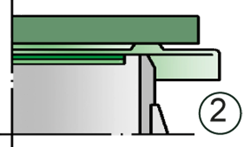
Detail X

Tank connection

Inbreathing

Outbreathing


 PROTEGO®
 Representative
 PARC / Service Partner