AL-DK

Vent Valve, Lift-actuated 

Features

Ventilación y respiración de tanques de techo flotante
El dispositivo se usa para el venteo y la respiración automáticos de tanques de techo flotante
Posición de reposo del techo flotante
En la posición de reposo del techo flotante, la válvula se abre automáticamente para evitar vacío o sobrepresión
Diferentes alturas
Debido a las diferentes alturas de la posición baja del techo flotante para los ajustes de operación y montaje, deben facilitarse dimensiones específicas
Conversión
Durante la conversión de las patas de apoyo del techo flotante de la posición de operación a la posición de mantenimiento, el émbolo debe extenderse
Ajuste mediante una opción de regulación
El ajuste se realiza mediante una opción de regulación con un pasador de bloqueo asegurado con una chaveta
No resistente a la transmisión de llamas
La válvula no es a prueba de transmisión de llama
Function and Description

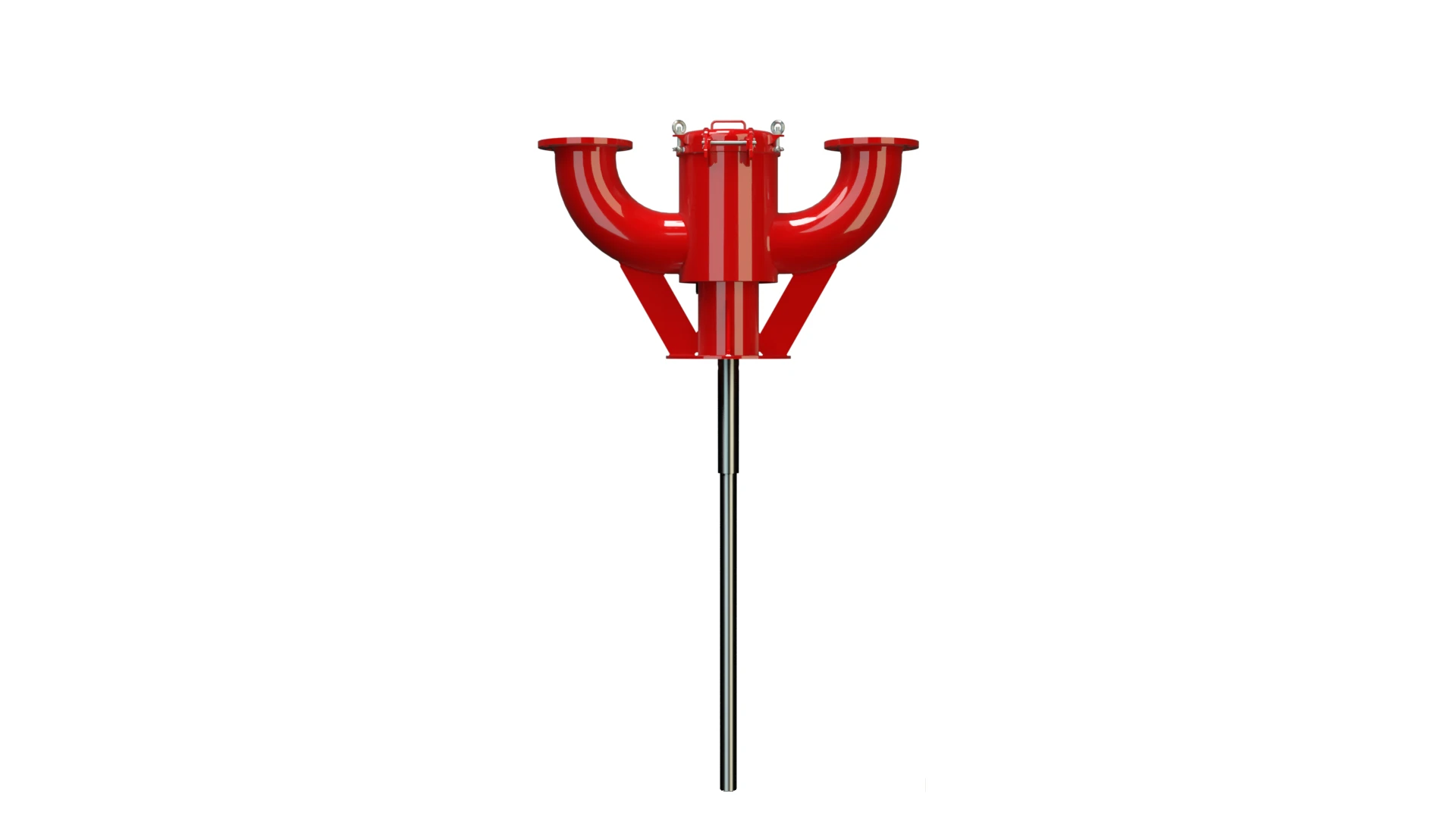
Automatic Venting Valves for Floating Roof Tanks
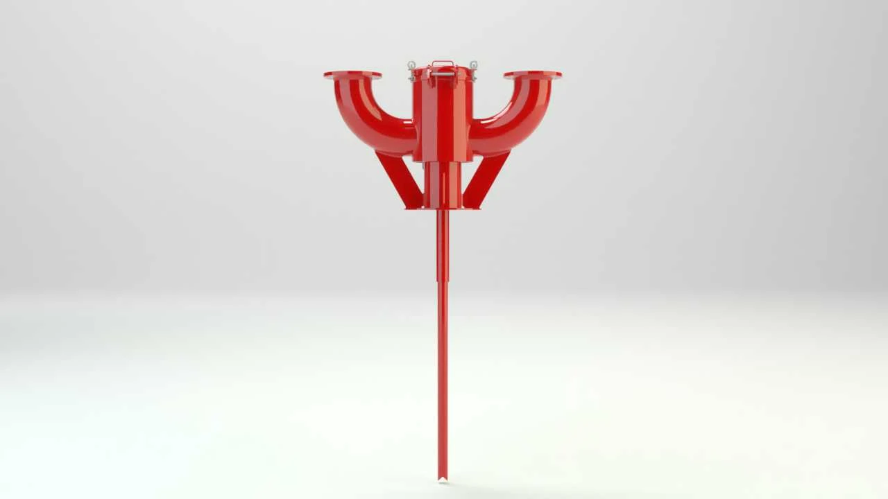
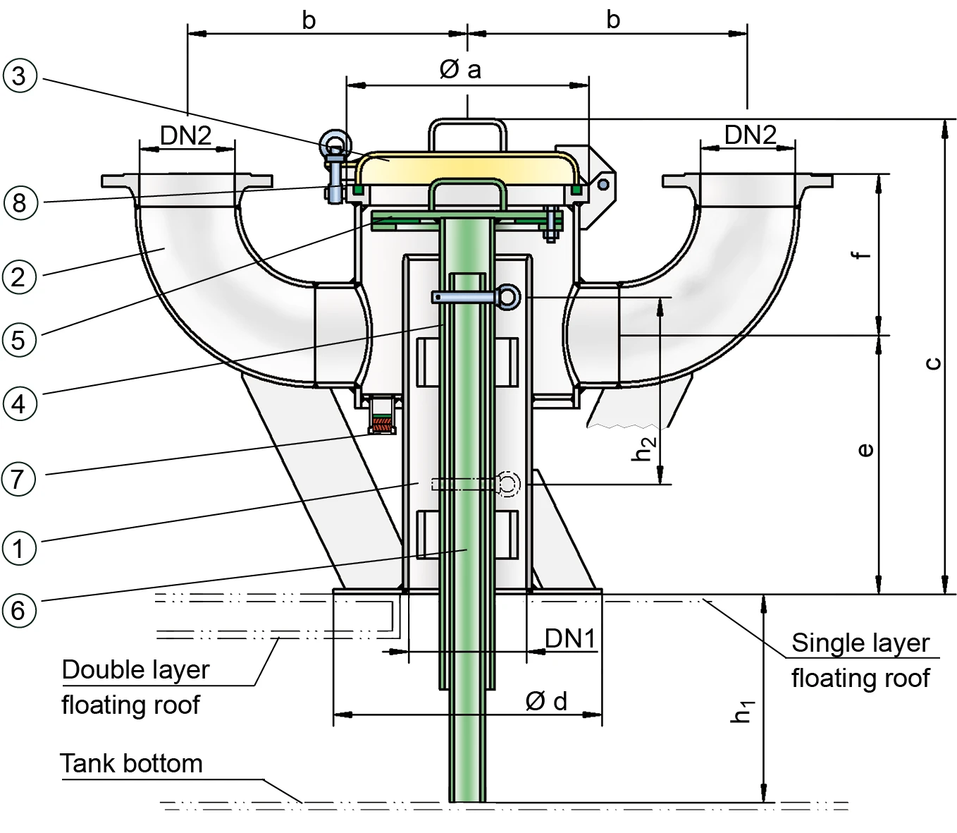
PROTEGO® Lift-Actuated Vent Valves Type AL-DK provide automatic venting of floating roof Toit flottant A floating roof is the roof of a tank that is fitted with floating chambers (pontoons) and lies on top of the liquid. tanks when the floating roof is lowered onto its supports and the tank is either drained or refilled. When the floating roof is in its lowest position, the valve is forced to open through lift Course Lift is the actual travel of the valve pallet from the main valve out of the closed position. actuation, which prevents inadmissible vacuum Dépression Vacuum is the pressure in an enclosed space that is lower than the ambient pressure. during final draining or inadmissible pressure during refilling.

Design of Valves

The PROTEGO® AL-DK valve consists of a housing Corps A housing is a solid shell, which surrounds a content, either protecting the content from external influences, or protecting the environment from the content. (1) with a sheet metal panel to be welded onto the floating roof or a flange for mounting on a mating flange, two or four connection nozzles (2) for installation of vent caps, cover (3), lift (4) including valve disc (5), lift pipe (6), and the condensate drain valve (7) which can be designed to be flame transmission proof. The condensate drain is sealed by a flat gasket attached to the valve disk (5). The cover (3) is sealed by a sealing cord Cordon d'étanchéité A sealing cord is a synthetic cord with a circular or square profile. It is used to seal off components. (8).

Dimensions for Different Floating Roof Heights

As the lowest position of the floating roof varies for operation and assembly, specify the dimensions h1 and h2: h1: Distance between the lower edge of sheet-metal panel (or mounting flange) and the tank bottom in lowest position of floating roof (operating position with an empty tank). h2: Distance between the floating roof in lifted maintenance position and the height of the floating roof in fully lowered operating position (operating position with an empty tank).

Conversion of Floating Roof Supports and Extension of the Plunger

If the floating roof supports are changed from operating position to maintenance position, the lift has to be extended as well. This is done with an adjustable locking pin that is secured with a split pin. The valve is not flame transmission proof. Based on a hazard analysis with regard to material selection and function, the valves have no potential ignition sources. As a result, they are not subject to the European Explosion Explosion Réaction brusque d’oxydation ou de décomposition entraînant une élévation de température, de pression ou des deux simultanément. Protection Directive (ATEX) when used in explosive atmospheres.
Product Data

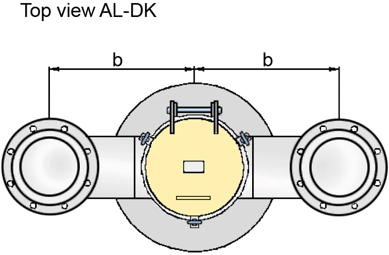
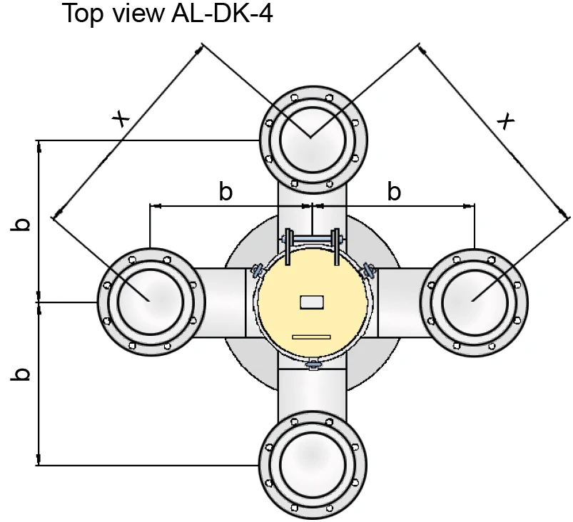
Maßtabelle für AL-DK und AL-DK-4

AL-DK AL-DK-4
DN1200 / 8" 200 / 8" 200 / 8" 200 / 8" 250 / 10" 250 / 10" 200 / 8" 200 / 8"
DN2 80 /3" 100 /4" 150 / 6" 200 / 8" 150 / 6" 200 / 8" 100 /4" 200 / 8"
a 350 / 13.78 350 / 13.78 350 / 13.78 350 / 13.78 350 / 13.78 350 / 13.78 350 / 13.78 350 / 13.78
b 465 / 18.31 465 / 18.31 465 / 18.31 515 / 20.28 465 / 18.31 515 / 20.28 465 / 18.31 650 / 25.59
c 870 / 34.25 870 / 34.25 870 / 34.25 870 / 34.25 870 / 34.25 870 / 34.25 870 / 34.25 870 / 34.25
d 450 / 17.72 450 / 17.72 450 / 17.72 450 / 17.72 450 / 17.72 450 / 17.72 450 / 17.72 600 / 23.62
e 345 / 13.58 360 / 14.17 385 / 15.16 415 / 16.34 385 / 15.16 415 / 16.34 415 / 16.34 415 / 16.34
f 460 / 18.11 445 / 17.52 285 / 11.22 370 / 14.57 285 / 11.22 367 / 14.45 445 / 17.52 370 / 14.57
x 658 / 25.91 920 / 36.22

Dimensiones en mm / pulgadas

Material

HousingSteel
Valve guideStainless Steel
GasketFPM

Special materials upon request

Tipo de bridas de conexión

EN 1092-1; Form B1andere Anschlüsse auf Anfrage
ASME B16.5 CL 150 R.F.

Other types upon request

Diagrama de flujo volumétrico

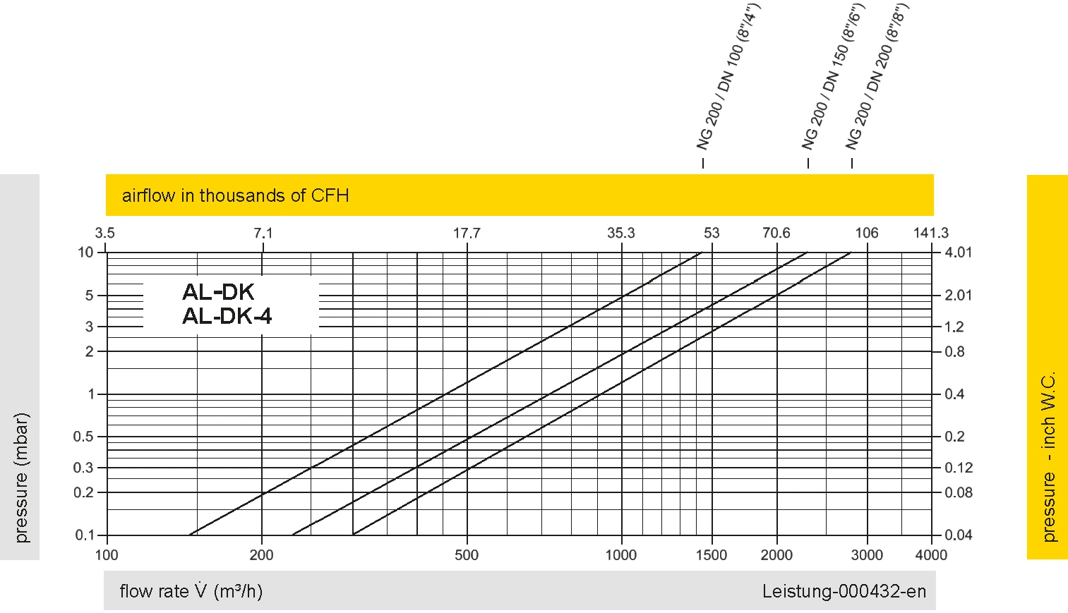
Los diagramas de flujo volumétrico han sido determinados con un banco de pruebas de caudal calibrado y certifi - cado por TÜV. El flujo volumétrico V. en [m³/h] y el CFH se refi eren a las condiciones estándar de referencia de aire según ISO 6358 (20°C, 1bar). La conversión a otras densidades y temperaturas están referidas en el Vol. 1: “Fundamentos Técnicos”.

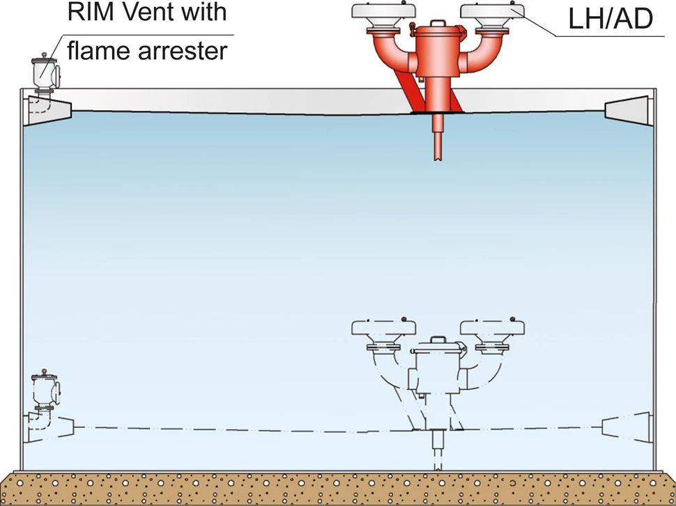
Application Examples for PROTEGO® AL-DK

Lift-actuated vent valves of type PROTEGO® AL-DK can be combined with vent caps type EB which are deflagration proof and resistant against endurance burning Endurance burning Stabilized burning for an unlimited time. . This ensures flame transmission proof ventilation.

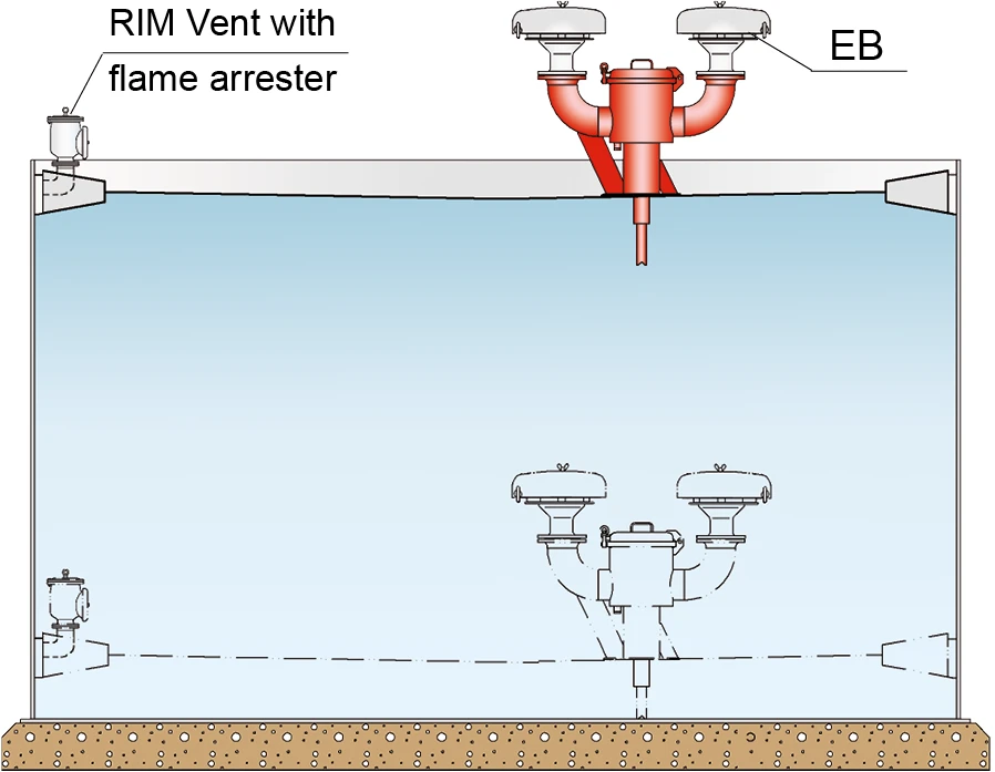
If resistance against endurance burning is not required the valves can alternatively be combined with PROTEGO® deflagration proof devices type PROTEGO® LH/AD. The applicable data sheets are available in volume 2 “ Deflagration Flame Arresters Arrête-flammes antidéflagration Flame arrester designed to prevent the transmission of a deflagration. It can be an end-of-line flame arrester or an in-line flame arrester. , end-of-line and Vent Caps”.

Applications

Depósitos de almacenamiento con techo flotante

Almacenamiento refrigerado y criogénico